Automatic sensor component-adhering assembly line and component-adhering method

A sensor and assembly line technology, applied in the direction of conveyor objects, transportation and packaging, etc., can solve the problems of low sensor placement efficiency, poor product consistency, complicated operation process, etc., to achieve good product consistency, ensure location, and improve product quality Effect

Active Publication Date: 2021-02-23
HRG INT INST FOR RES & INNOVATION
View PDF8 Cites 12 Cited by
  • Summary
  • Abstract
  • Description
  • Claims
  • Application Information

AI Technical Summary

Problems solved by technology

[0003] The technical problem to be solved by the present invention lies in: the technical problems of low sensor patch efficiency, poor product consistency and complicated operation process in the prior art

Method used


Image

  • Automatic sensor component-adhering assembly line and component-adhering method
  • Automatic sensor component-adhering assembly line and component-adhering method
  • Automatic sensor component-adhering assembly line and component-adhering method

Examples


Embodiment 1

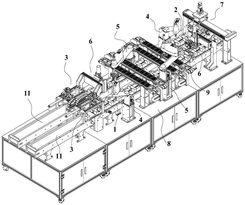
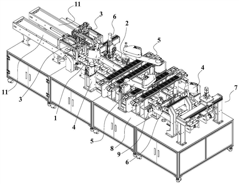
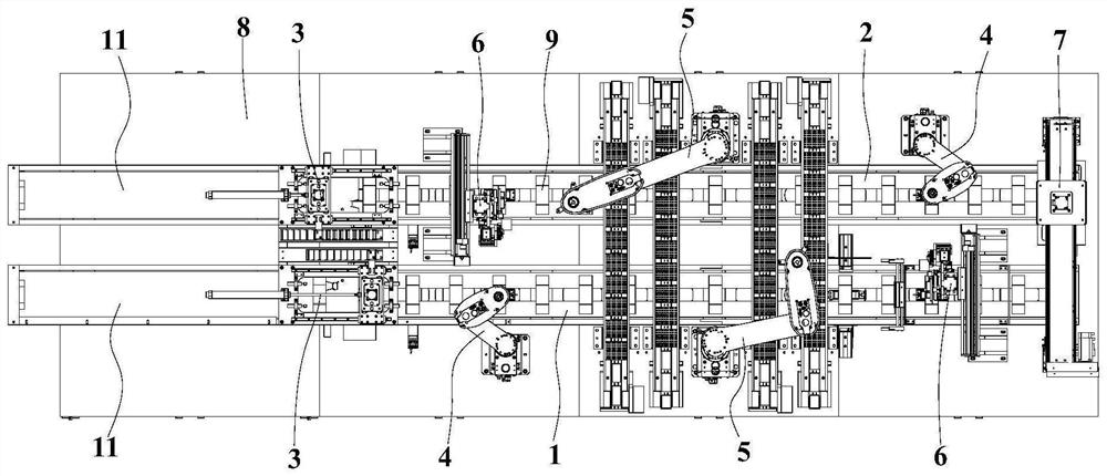
[0083] Such as Figure 1-3 As shown, a sensor automatic patch assembly line includes a first conveying mechanism 1, a second conveying mechanism 2, a material transfer mechanism 3, a glue spreading mechanism 4, a patch mechanism 5, a tape sticking mechanism 6, a handling and turning mechanism 7, a machine 8. Control unit.

[0084] In this embodiment, the main function of the frame 8 is to provide installation positions for the remaining components. The frame 8 is not limited to a specific shape, as long as the components can be installed and matched according to the requirements, and the corresponding functions can be realized. , the control unit in this embodiment adopts PLC, and PLC is an existing technology. Those skilled in the art can program it according to actual needs to realize the control function described in this embodiment. In this embodiment, the first The first conveying mechanism 1, the second conveying mechanism 2, the material transfer mechanism 3, the gluin...

Embodiment 2

[0141] The present invention also discloses a patching method using the automatic sensor patching assembly line described in Embodiment 1, which includes the following steps:

[0142] A. Feeding: Place the sensor 9 on the material conveyor belt 11 in front of the first conveying mechanism 1, the material conveyor belt 11 continues to run, and the sensor 9 is delivered to the stopper 111, the material conveyor belt 11 slips, and the front continues to move The sensor 9 is placed on the material conveyor belt 11, and then the sensor 9 is continuously transported to the front of the previous sensor 9, thereby realizing the accumulation of multiple sensors 9 in front of the stopper 111;

[0143] The material transfer mechanism 3 transfers the sensor 9 to be patched to the feeding end of the first conveying mechanism 1 for loading, and the side of the sensor 9 to be patched faces upward;

[0144] B. Conveying at equal intervals: the first conveying mechanism 1 drives the sensor 9 t...


PUM


Abstract

The invention relates to the field of sensor production, in particular to an automatic sensor component-adhering assembly line and a component-adhering method. The automatic sensor component-adheringassembly line comprises a machine frame, and a first conveying mechanism and a second conveying mechanism are arranged on the machine frame; the first conveying mechanism is sequentially provided witha material transferring mechanism, a gluing mechanism, a component-adhering mechanism and an adhesive tape pasting mechanism from the feeding end to the discharging end; a carrying turnover mechanismis arranged between the discharging end of the first conveying mechanism and the feeding end of the second conveying mechanism; and the second conveying mechanism is sequentially provided with a gluing mechanism, a chip mounting mechanism and an adhesive tape pasting mechanism from the feeding end to the discharging end. The component-adhering method comprises the following steps of feeding, conveying at equal intervals, gluing, component adhering, adhesive tape pasting, carrying and overturning and secondary component adhering. The automatic sensor component-adhering assembly line and the component-adhering method have the advantages that the sensor component adhering efficiency is high, the product consistency is good, and the operation process is simple and convenient.

Description

technical field [0001] The invention relates to the field of sensor production, in particular to a sensor automatic patch assembly line and a patch method, especially applied to the production of weighing sensors. Background technique [0002] A load cell is a type of force sensor used on load cell scales. It can convert the gravity acting on the measured object into a measurable output signal in a certain proportion. The performance indicators of the load cell mainly include linearity error, hysteresis error, repeatability error, creep, zero temperature characteristics and sensitivity temperature characteristics. In the production process of the load cell, one of the processes is to mount the sensor on the surface of the sensor. In the prior art, the Chinese invention patent application with the publication number CN107687888A discloses a production process for a digital load cell, which includes grinding , SMD, bridge wiring, warming, wire welding, module welding, sealin...

Claims


Application Information

Patent Timeline
Patent Type & Authority Applications(China)
IPC IPC(8): B65G47/90B65G47/52
CPCB65G47/90B65G47/52
Inventor 刘吉唐阳洋于振中李文兴
Owner HRG INT INST FOR RES & INNOVATION
Why Eureka
Try Eureka