
High-rotating-speed oil-gas separator for turbine engine

A technology of oil-gas separator and turbine engine, which is applied in the direction of engine components, machine/engine, and engine lubrication, etc., which can solve the problems of low separation efficiency, large influence, and structural size that cannot meet the volume and weight requirements of high-speed turbine engines. Achieve high separation efficiency, improve product integration, and simplify product structure

Active Publication Date: 2021-02-23
SICHUAN AEROSPACE ZHONGTIAN POWER EQUIP CO LTD
View PDF13 Cites 1 Cited by
  • Summary
  • Abstract
  • Description
  • Claims
  • Application Information

AI Technical Summary

Problems solved by technology

[0004] The purpose of the present invention is to provide a high-speed oil-gas separator for a turbine engine to solve the problem that the existing oil-gas separator is greatly affected by the engine working conditions, has low separation efficiency, and the structural size cannot meet the volume and weight requirements of a high-speed turbine engine. defect

Method used


Image

  • High-rotating-speed oil-gas separator for turbine engine
  • High-rotating-speed oil-gas separator for turbine engine
  • High-rotating-speed oil-gas separator for turbine engine

Examples


Embodiment 1

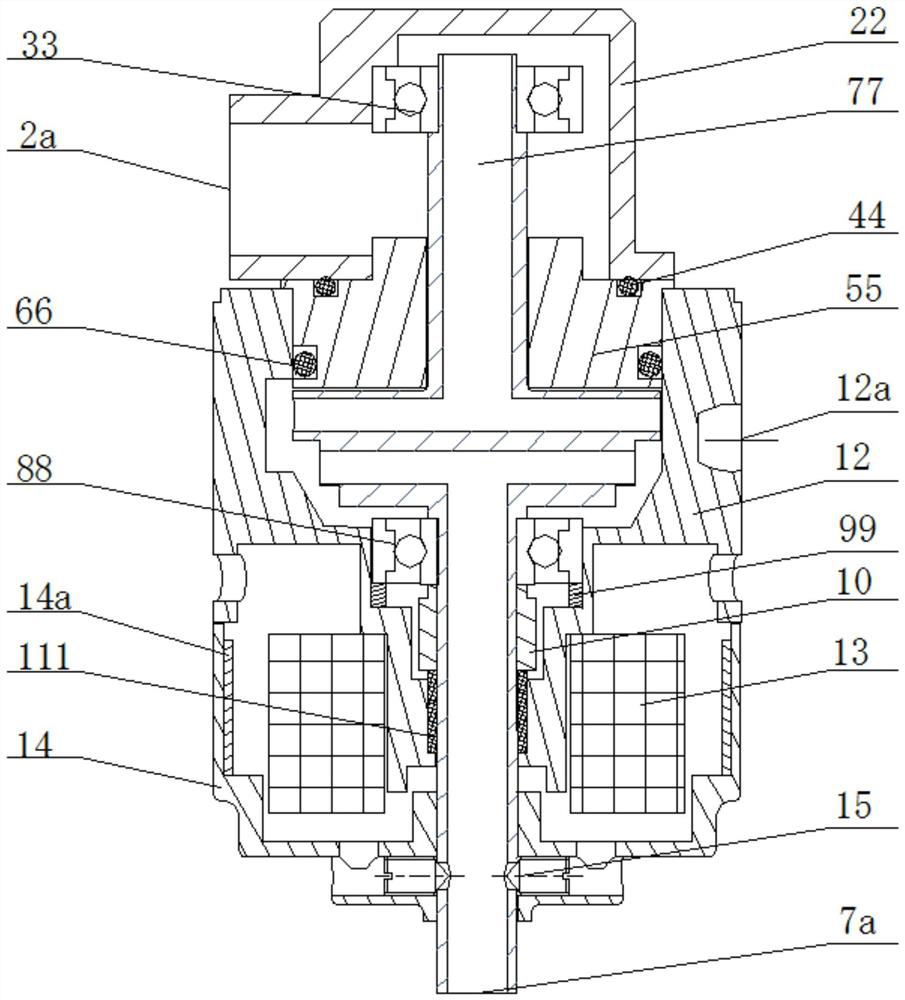
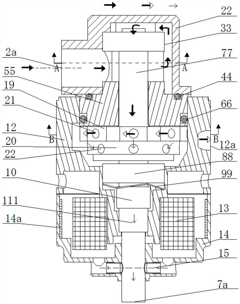
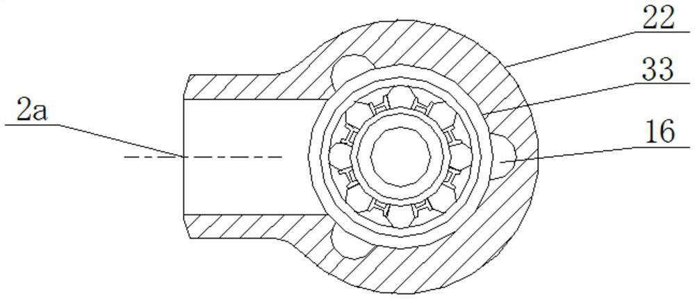
[0035] Such as figure 1 , 2 , 4, 5 and 6 A high-speed rotating oil-gas separator for a turbine engine, comprising a hollow rotating shaft 77, the upper part of the rotating shaft 77 is provided with an oil inlet chamber assembly, and the middle part of the rotating shaft 77 is provided with a separation chamber assembly, The lower part of the rotating shaft 77 is provided with a driving mechanism, and the separation chamber assembly includes a separator cavity 12 located on the outer periphery of the middle part of the rotating shaft 77, and a partition located at the middle part of the rotating shaft 77 in the separator cavity 12 layer, the first centrifugal disk 19 located at the upper part of the partition layer, the second centrifugal disk 20 located at the lower part of the partition layer, a plurality of first through holes 21 located at the outer periphery of the first centrifugal disk 19 and the A plurality of second through holes 22 on the outer periphery of the seco...

Embodiment 2

[0038] Such as Figure 4 As shown, on the basis of Example 1, the inner wall of the separator cavity 12 on the side where the oil outlet 12a is located is attached to the outer periphery of the first centrifugal disk 19 to form an abutment surface, and the The bonding surface is used as the starting point, and the second oil guiding groove 17 is provided on the inner wall of the separator cavity 12 along the direction of rotation of the rotating shaft 77 with successively increasing depths and communicates with the oil outlet 12a. The initial depth of the second oil guide groove 17 is zero, and the inner wall of the separator chamber 12 on the side where the oil outlet 12a is located is fitted to the outer periphery of the first centrifugal disk 19 to form a fitting surface without any lubricating oil thrown out. 77 rotates counterclockwise, the deeper the second oil guide groove 17 is, it is beneficial to the collection and flow discharge of lubricating oil subjected to centr...

Embodiment 3

[0040] Such as figure 1 , 2 , 5 and 6, on the basis of Example 1, the rotating shaft 77, the first centrifugal disc 19, the barrier layer and the second centrifugal disc 20 are integrally formed, and the first The centrifugal disc 19 communicates with the rotating shaft 77 on the upper part of the barrier layer, and the second centrifugal disc 20 communicates with the rotating shaft 77 on the lower part of the barrier layer. It is convenient for processing and assembly, and the product structure is simple.


PUM


Abstract

The invention discloses a high-rotating-speed oil-gas separator for a turbine engine, and particularly relates to the field of high-rotating-speed oil-gas separators. The high-rotating-speed oil-gas separator aims to overcome the defects that in the prior art, the influence of the working condition of an engine is large, and the structural size cannot meet the requirements of the high-rotating-speed turbine engine. The high-rotating-speed oil-gas separator comprises a hollow rotating shaft, an oil inlet cavity assembly is arranged on the upper portion of the rotating shaft, a separation cavityassembly is arranged in the middle of the rotating shaft, and a driving mechanism is arranged on the lower portion of the rotating shaft; and the separation cavity assembly comprises a separator cavity, a partition layer, a first centrifugal disc, a second centrifugal disc, a second oil guide groove and an oil outlet, wherein the partition layer is located in the separator cavity and located in the middle of the rotating shaft, the first centrifugal disc is located on the upper portion of the partition layer, the second centrifugal disc is located on the lower portion of the partition layer,the second oil guide groove is located in the separator cavity and communicates with a plurality of first through holes, and the oil outlet is located in the separator cavity and communicates with thesecond oil guide groove. The high-rotating-speed oil-gas separator is driven by power, is not affected by the working condition of the engine, is high in separation efficiency and can meet the requirements of the size and the weight of the high-rotating-speed turbine engine.

Description

technical field [0001] A high-speed oil-gas separator for a turbine engine, the invention belongs to the technical field of oil-gas separation, and specifically relates to the technical field of high-speed oil-gas separators. Background technique [0002] When the aero-engine is working, clean, low-temperature lubricating oil is transported to the rotating parts of the engine, thereby reducing friction and taking away the heat generated by friction. Under the effect of the pressure difference inside and outside the lubrication system, air will enter the system, and under the action of the high-speed rotating parts of the engine, the lubricating oil is mixed with the air to form lubricating oil emulsion and oil mist, which are transported to the oil return pump by the oil return pump. in the oil system. Moreover, in order to ensure the safe operation of the engine, the design capacity of the oil return pump is often greater than the oil supply, and it will also send a large ...

Claims


Application Information

Patent Timeline
IPC IPC(8): F01D25/18F02C7/06
CPCF01D25/18F02C7/06
Inventor 李纪永徐望李涛李芳马阳陈亮
Owner SICHUAN AEROSPACE ZHONGTIAN POWER EQUIP CO LTD
Learn More