Stainless steel double-row cylinder body welding structure

A welded structure, stainless steel technology, applied in the field of compressors, can solve the problems of long production cycle, waste of materials, explosion, etc., to achieve the effect of shortening manufacturing time, reducing operating costs, and saving use

Pending Publication Date: 2021-02-23
GUNAI HEAVY IND SUZHOU
View PDF0 Cites 0 Cited by
  • Summary
  • Abstract
  • Description
  • Claims
  • Application Information

AI Technical Summary

Problems solved by technology

But there are the following disadvantages: under the same strength, the product is heavy and wastes materials; molds need to be made, which is not suitable for single-piece production; the structure of the double-row cylinder is complex, the casting process is difficult to formulate, and the yield is only about 30%; it is not resistant to low temperature ( minus 80°C) and not resistant to corrosive gases
[0003] Since the traditional cylinder block design and manufacture process basically uses casting molding, it is necessary to produce molds and sand molds, which has a long production cycle and high cost
Moreover, the structure of the double-row cylinder is relatively complicated. It is made of cast stainless steel, which has poor fluidity and a high scrap rate, and the stainless steel cast cylinder is prone to defects, and there are factors such as instability in future operation and maintenance. If the cylinder exists Shrinkage, porosity, cracks and other defects, there may be gas leakage problems during operation
Once a leak occurs, the entire intermediate link of production will be interrupted, resulting in scrapped materials, increasing the operating costs of the enterprise, and may also cause safety accidents such as explosions and poisoning

Method used


Image

  • Stainless steel double-row cylinder body welding structure
  • Stainless steel double-row cylinder body welding structure
  • Stainless steel double-row cylinder body welding structure

Examples


Embodiment

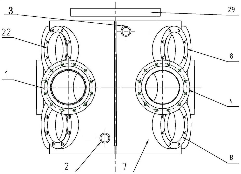
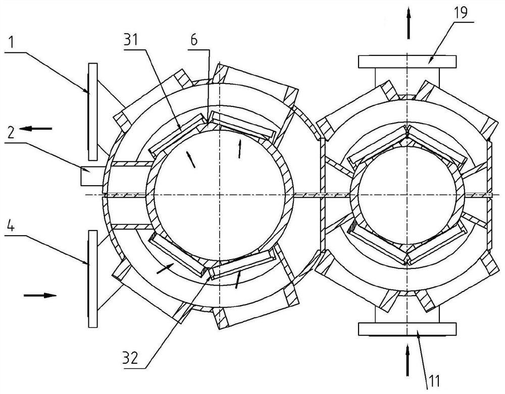
[0027] When the primary inner cylinder 6 and the secondary inner cylinder 13 need to be cooled, the cooling gas enters the secondary inner cylinder 13 from the primary air inlet flange 4 installed on the primary outer ring 7 After the primary inlet valve flange 32 on the upper level, it reaches the secondary inner cylinder 6 and cools it, and then passes through the primary exhaust valve flange 31 fixed on the secondary inner cylinder 6 and is installed in the secondary inner cylinder 6. The first-level exhaust port flange 1 on the first-level outer ring 7 is discharged;

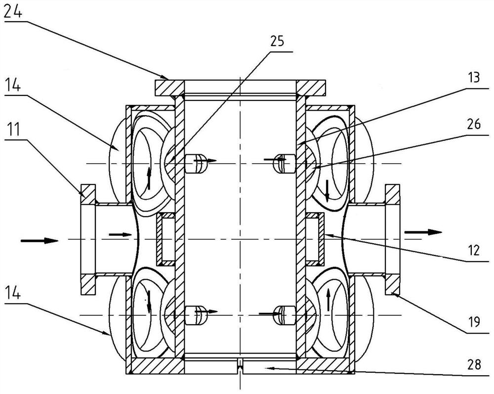
[0028] At the same time, the cooling gas enters the secondary intake valve flange 25 fixed on the secondary inner cylinder 13 from the secondary inlet flange 11 installed on the secondary outer ring 33, and then reaches the secondary inner cylinder 13 and cool it, and then through the secondary exhaust valve flange 26 fixed on the secondary inner cylinder 13 and then discharged from the secondary exhaust por...


PUM


Abstract

The invention discloses a stainless steel double-row cylinder body welding structure. The stainless steel double-row cylinder body welding structure comprises a first-stage inner cylinder barrel and asecond-stage inner cylinder barrel which are connected together through a middle partition plate. The stainless steel double-row cylinder body welding structure comprises an air cavity for cooling the first-stage inner cylinder barrel and the second-stage inner cylinder barrel and a water cavity, and water in the water cavity circularly flows on the outer side of the first-stage inner cylinder barrel and the outer side of the second-stage inner cylinder barrel. A cylinder body is designed into a simple double-row cylinder body structure, casting cylinder body waste products are avoided, the cylinder body manufacturing time is shortened, raw materials are saved, and resources are saved. Compared with an existing single stainless steel double-row cylinder body welding structure with the cost more than one million, the single stainless steel double-row cylinder body welding structure in the invention has the advantages that the cost can be saved by hundreds of thousands of yuan, and theoperation cost is reduced.

Description

technical field [0001] The invention relates to the field of compressors, in particular to a stainless steel double-row cylinder body welded structure. Background technique [0002] With the continuous improvement of production technology, the types of compressors used in the coal chemical industry have shown a diversified development. Among them, the role of labyrinth compressors in the coal chemical industry has become increasingly prominent. In particular, there are challenges in the production and manufacture of double-row cylinder blocks for labyrinth compressors with BOG cryogenic media. The original general cylinder block manufacturing process materials are generally made of gray cast iron and ductile iron, which are manufactured by casting process. But there are the following shortcomings: under the same strength, the product weighs a lot and wastes materials; it needs to make a mold, which is not suitable for single-piece production; the structure of the double-ro...

Claims


Application Information

Patent Timeline
Patent Type & Authority Applications(China)
IPC IPC(8): F04B39/12F04B39/06
CPCF04B39/06F04B39/122
Inventor 冯学仙赖兴雨邱坤伦曹火光
Owner GUNAI HEAVY IND SUZHOU
Why Eureka
Try Eureka