
Gas distribution device with spiral structure

A gas distribution device and spiral structure technology, applied in separation methods, evaporator accessories, evaporation, etc., can solve the problems of erosion and wear of the distribution device, polluted crystalline particles, and structural damage of the distribution device, and achieve the elimination of the dead angle of the gas flow field. The effect of reducing drying and evaporation time and increasing load elasticity

Pending Publication Date: 2021-02-26
JIANGSU JINGYUAN ENVIRONMENTAL PROTECTION
View PDF0 Cites 0 Cited by
  • Summary
  • Abstract
  • Description
  • Claims
  • Application Information

AI Technical Summary

Problems solved by technology

[0003] The existing gas distribution devices generally have the following defects: 1. After distribution, the gas flow field does not mix the droplets uniformly, which leads to a long time for the overall drying and evaporation, and some droplets cannot be completely evaporated within the effective time; 2. . After the distribution, the gas flow field is not ideal for the mixing and diversion trajectory of the droplets, causing the droplets to touch the wall of the drying equipment before they are completely evaporated, causing the wall to stick to the wall, resulting in corrosion of the evaporation equipment, or pollution of crystalline particles; 3. When the gas distribution device handles different gas volumes, the flow field effect is very different, so that the whole set of evaporation equipment can only evaporate and dry a fixed amount of droplets, and the drying effect on other processing conditions is very poor; 4. The structure of the gas distribution device is not good. Reasonable, the pressure difference between the front and back of the gas treatment is large, and a more powerful air supply and induction device is required; 5. The structure of the gas distribution device is unreasonable, and the gas will erode and wear the distribution device, which will easily cause damage to the structure of the distribution device and affect the use. 6. The structure of the gas distribution device is unreasonable, which makes the overall device size too large, and it is impossible to install a matching gas distribution device in some places where the space is limited
7. The matching between the gas distribution device and the rotary atomizer is not high, which leads to difficulties in the installation, disassembly and maintenance of the atomizer, which affects the efficiency of the normal operation of the system

Method used


Image

  • Gas distribution device with spiral structure
  • Gas distribution device with spiral structure
  • Gas distribution device with spiral structure

Examples


Embodiment 1

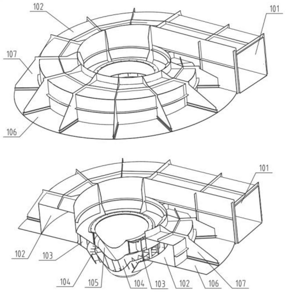
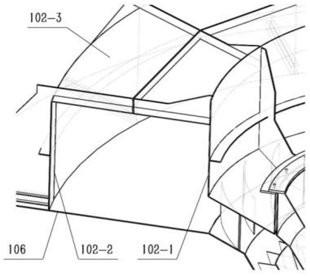
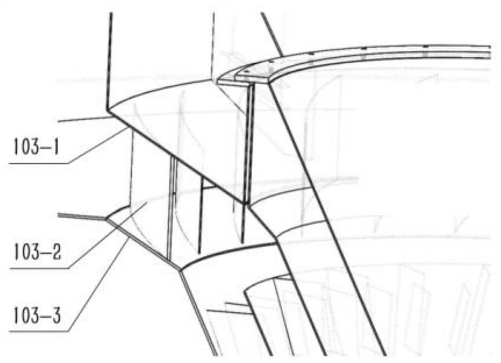
[0028] Such as figure 1 with Figure 4As shown, a gas distribution device with a spiral structure includes a device body and a reinforcement structure 107 detachably connected to the device body. The device body includes a bottom plate 106, and an air inlet 101 is arranged on the bottom plate. The straight tube structure is used at the inlet, and the length of the straight tube at the inlet is just enough to ensure the effective integration of the flow field at the inlet, while minimizing the overall size of the device; when the length of the straight tube at the inlet is lower than the design value, it will It leads to disorder of the intake air flow field, and when it is higher than the design value, it will lead to an increase in the overall size of the gas distribution device. The air inlet design has a large intake velocity span, which increases the load elasticity that the gas distribution device can handle. When dealing with different gas flows , the gas distribution e...


PUM


Abstract

The invention discloses a gas distribution device with a spiral structure. According to the gas distribution device with the spiral structure, a gas inlet is formed in a bottom plate, the gas inlet isof a straight pipeline structure, the straight pipeline structure is connected with a spiral channel, a gas guide channel is arranged below the inner side of the spiral channel, a gas outlet is connected below the guide channel, the gas outlet is of a conical structure, and the gas outlet comprises a partition plate; the gas outlet is divided into an outer side outlet flow channel and an inner side outlet flow channel by the partition plate, the outer side outlet flow channel is provided with a second-level guide vane, the inner side outlet flow channel is provided with a third-level guide vane, a detachable central cylinder cone is arranged above the center of the bottom plate, and a reinforcing structure is arranged above the bottom plate for the gas inlet, the spiral channel and the guide channel. The gas inlet ensures that a gas inlet flow field can be effectively integrated, meanwhile, the boundary dimension of the device is reduced to the maximum extent, the horizontal flow velocity and the axial flow velocity required by gas are integrated through the gas flow guide channel, gas transition to the gas outlet section is smoother, and dead corners of the gas flow field are eliminated.

Description

technical field [0001] The invention relates to the technical fields of chemical industry and biological equipment, in particular to a gas distribution device with a spiral structure. Background technique [0002] Evaporation and drying of liquids by means of rotary atomization evaporation is a common drying and granulation method. The main method of rotary atomization is that when the liquid is sent to the high-speed rotating atomizing disc, due to the action of centrifugal force, the liquid is stretched into a thin film or drawn into filaments (depending on the rotational speed and the amount of slurry), and breaks at the edge of the atomizing disc Disperses into droplets. The size of the droplets depends on the rotation speed and the amount of liquid handled. The atomizer can ensure that the particle size distribution of the atomized droplets does not change significantly when the liquid flow rate does not change greatly. The atomized liquid is fully and uniformly mixe...

Claims


Application Information

Patent Timeline
Patent Type & Authority Applications(China)
IPC IPC(8): B01D1/22B01D1/00B01D1/14B01D1/30
CPCB01D1/0041B01D1/14B01D1/222B01D1/30
Inventor 李武林徐俊秀季献华李宽王辰仲明薛军峰
Owner JIANGSU JINGYUAN ENVIRONMENTAL PROTECTION
Learn More