Metal cutting machine tool capable of achieving rapid clamping
A metal cutting and machine tool technology, applied in metal processing machinery parts, metal processing equipment, clamping, etc., can solve problems such as deformation and difficult adjustment of clamping force
- Summary
- Abstract
- Description
- Claims
- Application Information
AI Technical Summary
Problems solved by technology
Method used
Image

Examples
Embodiment 1
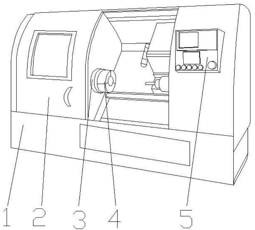
[0033] Such as Figure 1-2 , the present invention provides a technical solution: a metal cutting machine tool that can be quickly clamped, including a main body 1, a control panel 5 is arranged on the right side of the front top of the main body 1, and a box door 2 is movably connected to the left side of the front top of the main body 1 An auxiliary clamping device 3 is provided in the middle of the inner wall on the left side of the main body 1 , and a clamping device 4 is fixedly connected to the right side of the auxiliary clamping device 3 .
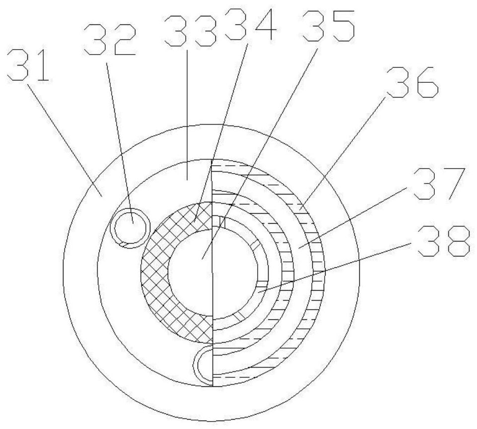
[0034] Wherein, the auxiliary clamping device 3 includes a base 31, the top of the base 31 is fixedly connected with a force plate 33, the inside of the force plate 33 is fixedly connected with a booster plate 37, and the inside of the force plate 33 is located on both sides of the booster plate 37. The side is fixedly connected with an elastic force plate 36, the surface of the force plate 33 is provided with a fixed groove 32, th...
Embodiment 2
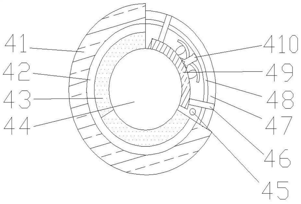
[0037] Such as Figure 1-3As shown, on the basis of Embodiment 1, the present invention provides a technical solution: the clamping device 4 includes a bottom plate 41, the bottom of the bottom plate 41 is fixedly connected with a fixed column 45, and the inside of the bottom plate 41 is provided with a support block 47, the support block The inner surface of 47 is fixedly connected with fixed ring 48, and the top of base plate 41 is fixedly connected with connection block 42, and the inside of connection block 42 is fixedly connected with fixed frame 410, and the top of connection block 42 is movably connected with clamping block 43, and the clamping block The middle part of 43 is provided with clamping mouth 44, and clamping block 43 is provided with clamping tooth 49 near the side of clamping mouth 44, and the side of clamping tooth 49 away from clamping mouth 44 is provided with protruding piece 46.
[0038] During use, the workpiece is placed in the connecting hole on the...
Embodiment 3
[0040] Such as Figure 1-5 As shown, on the basis of Embodiment 1 and Embodiment 2, the present invention provides a technical solution: the inside of the fixed plate 34 is fixedly connected with a front push plate 8, and the inside of the front push plate 8 is fixedly connected with a blocking plate 6 to block A connecting ring 9 is fixedly connected to the inside of the plate 6 , and a deformed plate 10 is arranged inside the connecting ring 9 , and a rubber sheet 7 is fixedly connected to the side of the deformed plate 10 away from the connecting ring 9 .
[0041] Wherein, the inner walls of both sides of the fixed frame 410 are fixedly connected with protective blocks 16, and the middle parts of both sides of the fixed frame 410 are fixedly connected with arc-shaped parts 11, and the inner cavity bottom of the arc-shaped parts 11 is provided with fixed teeth 12, and The middle position of the bottom is fixedly connected with a support piece 13 , the top of the inner cavity...
PUM
 Abstract
Description
Claims
Application Information
 - R&D
- Intellectual Property
- Life Sciences
- Materials
- Tech Scout
- Unparalleled Data Quality
- Higher Quality Content
- 60% Fewer Hallucinations
Browse by: Latest US Patents, China's latest patents, Technical Efficacy Thesaurus, Application Domain, Technology Topic, Popular Technical Reports.
© 2025 PatSnap. All rights reserved.Legal|Privacy policy|Modern Slavery Act Transparency Statement|Sitemap|About US| Contact US: help@patsnap.com