Gas relay for detecting transformer faults in real time, and diagnosis method thereof

A gas relay and transformer failure technology, applied to transformer/inductance parts, instruments, circuits, etc., can solve the problems of untimely gas detection, transformer damage, poor effectiveness, etc., and achieve rapid detection, accurate diagnosis, and strong effectiveness Effect

Pending Publication Date: 2021-02-26
ELECTRIC POWER RES INST STATE GRID SHANXI ELECTRIC POWER +1
View PDF1 Cites 2 Cited by
  • Summary
  • Abstract
  • Description
  • Claims
  • Application Information

AI Technical Summary

Problems solved by technology

[0005] In order to solve the problem of transformer damage or even burnout caused by misoperation of the transformer gas relay in the prior art due to other interferences that cause alarms, untimely gas detection and poor effectiveness of a single detection method, etc., and to improve the reliability of safe operation of the transformer, the purpose of the present invention is to , providing a gas relay for real-time detection and diagnosis of transformer faults and a method for identifying and judging transformer faults, quickly detecting whether the gas accumulated in the gas relay is a fault-produced gas or a non-fault-produced gas, by detecting the smell and composition of the gas , Color comprehensive research and judgment of the severity of the transformer failure, the device of the present invention quickly sends diagnostic information to the transformer operator through the cloud platform after detection, and can diagnose the transformer operation status before the transformer develops into a serious fault, and provide maintenance and repair for the transformer operator Gain valuable processing time and prevent transformer damage due to untimely processing

Method used


Image

  • Gas relay for detecting transformer faults in real time, and diagnosis method thereof
  • Gas relay for detecting transformer faults in real time, and diagnosis method thereof
  • Gas relay for detecting transformer faults in real time, and diagnosis method thereof

Examples


no. 1 example

[0067] The first embodiment: a gas relay for real-time detection of transformer faults

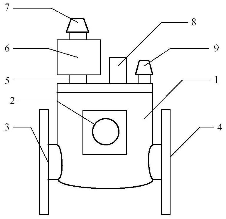
[0068] Such as figure 1 As shown, the present invention provides a gas relay for real-time detection of transformer faults, comprising: a gas relay body 1, an observation window 2, an oil inlet 3, an oil outlet 4, a first air pipe 5, a bottle to be inspected 6, and a gas relay Deflation plug 7, collection and transmission unit 8 and probe 9.

[0069] The bottle 6 to be inspected is a transparent container, which is used to collect the gas released inside the gas relay body 1. One end of the bottle 6 to be inspected is connected to the gas relay body 1 through the first air pipe 5, and the other end is connected to the air release plug of the gas relay through the second air pipe. 7 phase connections.

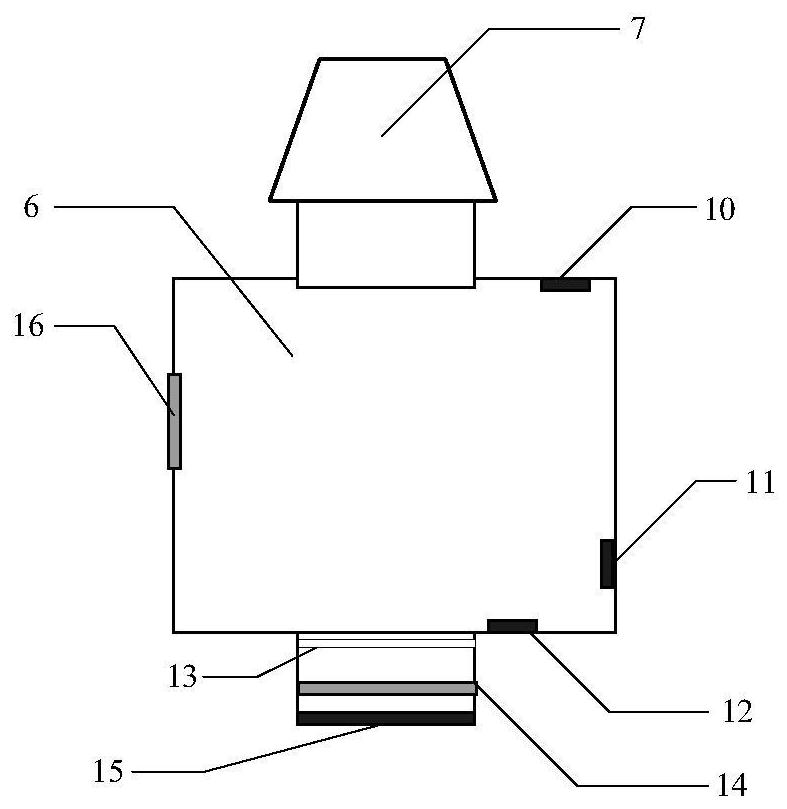
[0070] Such as figure 2 As shown, a faulty gas detection module connected to the collection and sending unit 8 is set in the bottle 6 to be inspected to detect whether the bottle 6 to be...

no. 2 example

[0091] Second embodiment: a diagnostic method for real-time detection of transformer faults

[0092] Such as Figure 4 As shown, the second embodiment of the present invention provides a diagnostic method using the above gas relay for real-time detection of transformer faults, comprising the following steps:

[0093] Step 1, gas accumulation occurs inside the transformer. If the pressure sensor 15 detects that the gas pressure inside the gas relay body 1 reaches the threshold K1, the air intake solenoid valve 14 is controlled to open, and the gas inside the gas relay body 1 passes through the intake solenoid valve 14 and the filter. The oil net 13 enters the bottle 6 to be inspected; after that, if the pressure sensor 15 detects that the gas pressure inside the gas relay body 1 drops below the threshold K1, the intake solenoid valve 14 is controlled to close.

[0094] Step 2, the hydrocarbon detection sensor 10 arranged inside the bottle 6 to be inspected detects whether the ...

example 1

[0124] Example 1, the accumulation of gas in a transformer gas relay caused the gas relay to send out an alarm signal, and the site could not immediately judge whether it was gas or air caused by the internal fault of the transformer. Utilizing the technology of the invention, the hydrocarbon sensor detects hydrocarbon gas at 16.5ppm, and the characteristic value of Pq is 2. The electronic nose sensor detects the irritating odor, and the characteristic value of Pd is 2. The gas color detected by the color change sensor is yellow, and the characteristic value of Ps is 2. Through the comprehensive detection and diagnosis, the P is 17.8. It is judged that there is a critical fault inside the transformer, and timely prompts the substation operators to stop the power for emergency treatment. After a timely power outage and inspection, it was found that there were serious discharge traces inside the transformer. Through timely power outage and effective measures, further damage to t...


PUM


Abstract

The invention relates to a gas relay for detecting transformer faults in real time, and a diagnosis method thereof. The gas relay comprises a gas relay body, an oil inlet, an oil outlet, a first gas pipe, a to-be-detected bottle, a gas relay vent valve and an acquisition and sending unit, and a fault gas detection module connected with the acquisition and sending unit and arranged in the to-be-detected bottle is used for detecting whether the to-be-detected bottle contains hydrocarbon gas, the concentration of the hydrocarbon gas, the gas color and irritating odor gas or not; and if the pressure sensor detects that the gas pressure in the gas relay body reaches a threshold K1, the gas inlet electromagnetic valve is controlled to be opened, and gas in the gas relay body enters the to-be-detected bottle through the gas inlet electromagnetic valve and the oil filter screen. Compared with the prior art, the method has the advantages that the severity degree of the transformer faults is comprehensively evaluated, extremely precious time is gained for operation, maintenance and overhaul of the transformer, and traditional operation personnel do not need to go to a transformer substationto take gas and return the gas to a laboratory for detection.

Description

technical field [0001] The invention belongs to the technical field of power equipment quality detection, and more specifically relates to a gas relay and a diagnostic method for real-time detection of transformer faults. Background technique [0002] The gas relay mainly plays a basic protective role inside the power transformer. The application of the gas relay shows that when the insulation of the transformer is rapidly decomposed or the transformer body has a discharge fault, the gas relay often quickly reflects the fault degree and disconnects in time. Power supply can effectively reduce the loss caused by transformer failure and avoid the expansion of transformer accidents. However, due to the air entering the transformer, temperature drop, etc., the gas relay often malfunctions (partially because air is mixed into the gas relay) and causes an alarm or trip. In fact, the transformer is not faulty, which seriously affects the reliable operation of the transformer. [0...

Claims


Application Information

Patent Timeline
Patent Type & Authority Applications(China)
IPC IPC(8): G01N21/25G01N33/00H01H35/26H01F27/40G06F17/10
CPCG01N21/25G01N33/0031G06F17/10H01F27/402H01F2027/404H01H35/26
Inventor 俞华刘宏王伟王健一李国栋程涣超刘星廷穆广祺遇心如梁宁川上官明霞解涛王海鹏李劲松王帅陈青松
Owner ELECTRIC POWER RES INST STATE GRID SHANXI ELECTRIC POWER
Why Eureka
Try Eureka