Augmented reality display system

A display system and augmented reality technology, applied in the field of optics, can solve problems such as poor viewing experience, uneven light matching, affecting imaging quality, etc., to achieve the effect of convenient adjustment, improving experience comfort, and avoiding light crosstalk

Pending Publication Date: 2021-02-26
SVG TECH GRP CO LTD +1
View PDF0 Cites 3 Cited by
  • Summary
  • Abstract
  • Description
  • Claims
  • Application Information

AI Technical Summary

Problems solved by technology

However, the above situation is an ideal situation. In the process inspection process, the light matched with the first diffractive waveguide lens 1-1 cannot be completely diffracted and transmitted by the lens, and part of the light will continue to pass through the second diffractive waveguide lens 1-2 and the third

Method used


Image

  • Augmented reality display system
  • Augmented reality display system
  • Augmented reality display system

Examples


Embodiment 1

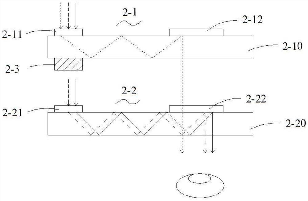
[0033] See Figure 2 to Figure 4 , the augmented reality display system shown in an embodiment of the present invention includes:

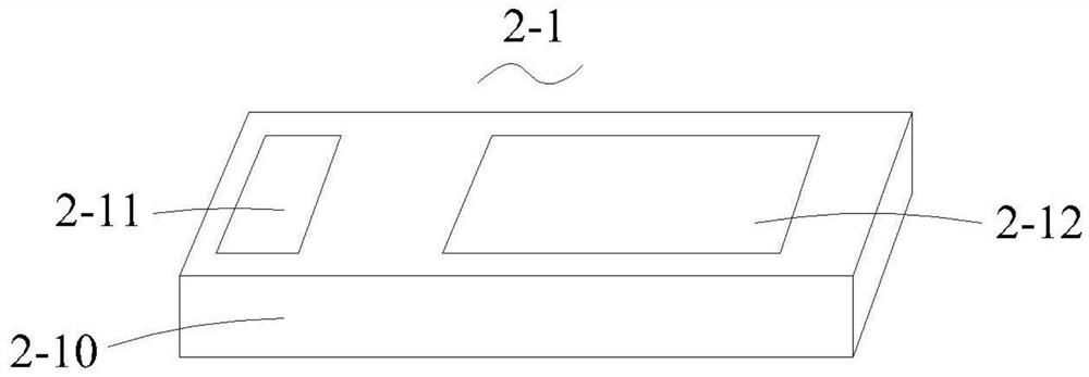
[0034] A laser light source (not shown) is used to provide incident image light. Of course, in other embodiments, it can also be other light sources such as LED, LCD or OLED. A first diffractive waveguide lens 2-1 and a second diffractive waveguide lens 2-2 are arranged at the irradiation place of the laser light source, and each diffractive waveguide lens includes a lens body and a functional area arranged on the lens body, specifically: the first The diffractive waveguide lens 2-1 includes a first lens body 2-10, a first coupling region 2-11 disposed on the first lens body 2-10, and a first coupling region 2-10 disposed on the first lens body 2-10. out of the region 2-12; the second diffractive waveguide lens 2-2 includes a second lens body 2-20, a second coupling region 2-21 disposed on the second lens body 2-20, and a second lens body dispose...

Embodiment 2

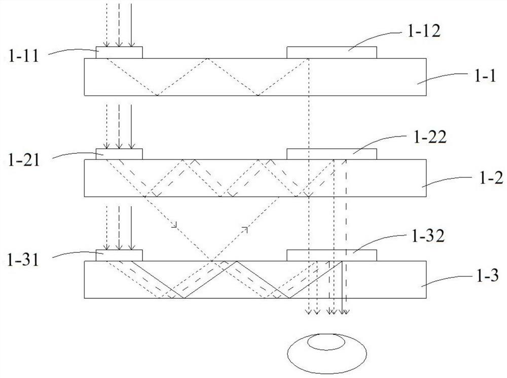
[0041] See Image 6 , in this embodiment, other structures of the augmented reality display system of the present invention are the same as those in Embodiment 1, except that the diffractive waveguide lens 3-1 in this embodiment adopts the three-region diffractive waveguide lens shown in the figure, specifically Yes, the diffractive waveguide lens 3-11 includes a lens body 3-10, an in-coupling area 3-11, a turning area 3-12 and an out-coupling area 3-13 arranged on the lens body 3-10. The incident image light is coupled to the diffractive waveguide lens 3-1, firstly enters the in-coupling area 3-11, and is diffracted by the nanostructure. The angle of the diffracted light satisfies the total reflection of the waveguide. The light is deflected, transmitted to the outcoupling region 3-13, diffracted by the nanostructure, and output to the human eye. Wherein, the image light is incident from the in-coupling area 3-11 of the waveguide lens, transmitted to the out-coupling area 3-...


PUM

PropertyMeasurementUnit
Thicknessaaaaaaaaaa
Heightaaaaaaaaaa
Transmittanceaaaaaaaaaa

Abstract

The invention relates to an augmented reality display system, which comprises a light source, at least two diffractive waveguide lenses and at least one light filtering layer used for isolating unnecessary light, wherein the light source is used for providing image light; each diffractive waveguide lens comprises a lens body and a functional area arranged on the lens body; and the light filteringlayer is arranged between the two diffractive waveguide lenses, and a dielectric grating is arranged on the light filtering layer. According to the augmented reality display system, the light filtering layer is arranged between every two diffractive waveguide lenses, so that independent control of waveband light of each diffractive waveguide lens can be realized, then light disorder can be eliminated, phenomena such as image chromatic aberration ghosting caused by light crosstalk can be avoided, and experience comfort can be improved. Moreover, by adjusting structural parameters of the dielectric grating, the resonance of a guide film can be excited, the adjustment is convenient, and a high-efficiency light filtering effect is achieved.

Description

technical field [0001] The invention relates to an augmented reality display system, which belongs to the field of optical technology. Background technique [0002] Augmented reality (AR) technology is a new technology that "seamlessly" integrates real world information and virtual world information. It not only shows real world information, but also displays virtual information at the same time. The two kinds of information complement each other. overlay. In visual augmented reality, users use the helmet display to recombine the real world with computer graphics, and then they can see the real world surrounding it. Most of the current mainstream near-eye augmented reality display devices use the optical waveguide principle. For example, Lumus realizes the AR display through the array grating design, and its display has the effect of pupil dilation, but there is a blind effect, which affects the viewing experience. Microsoft uses three layers of diffractive waveguide lens...

Claims


Application Information

Patent Timeline
IPC IPC(8): G02B27/01
CPCG02B27/0101G02B2027/011
Inventor 罗明辉乔文李玲熊金艳李瑞彬周振陈林森
Owner SVG TECH GRP CO LTD
Why Eureka
Try Eureka