Transverse modulation KDP type electro-optic Q switch

An electro-optic and switching technology, applied in circuits, lasers, electrical components, etc., can solve problems such as temperature difference, processing deviation, crystal optical quality is very sensitive, switching electrode preparation is difficult, switching performance is unstable, etc., and the effective electro-optic coefficient is large. , small natural birefringence, large allowable range

Active Publication Date: 2021-02-26
HENAN INST OF ENG
View PDF10 Cites 1 Cited by
  • Summary
  • Abstract
  • Description
  • Claims
  • Application Information

AI Technical Summary

Problems solved by technology

In this way, on the one hand, ring-shaped electrodes must be used, the switch shape and electrode preparation are difficult, and the electric field is not easy to be uniform, resulting in insufficient switching and low dynamic extinction ratio; on the other hand, the half-wave voltage is high and cannot be adjusted.
[0005] Some researchers have proposed a way to use transverse modulation. The crystal is cut at 45°-z, and an electric field is applied along the z-axis. The voltage can be reduced by increasing the aspect ratio, but there is natural birefringence, which needs to be compensated by a double crystal. Since the direction of light transmission and the optical axis are at 90°, the natural birefringence is the largest, and it is also most affected by temperature, resulting in switching performance. Extremely unstable, very sensitive to the temperature difference between two crystals, processing deviation and crystal optical quality, etc., so it has not been practically used

Method used


Image

  • Transverse modulation KDP type electro-optic Q switch
  • Transverse modulation KDP type electro-optic Q switch

Examples


Embodiment 1

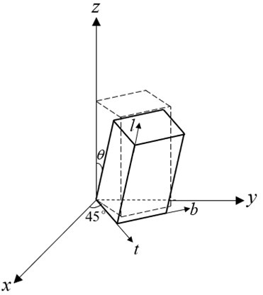
[0021] In this example, the DKDP crystal is used to prepare the electro-optical Q switch for lateral modulation, and the cut shape of the Q switch crystal is designed as , the size of a single crystal is 9mm×9mm×10mm (thickness t ×width b × length l ), applied to a laser with a laser wavelength of 1064 nm.

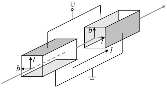
[0022] Cut two pieces of DKDP crystals of the same specification according to the designed cutting shape and size, polish and coat the two ends of the length direction with a 1064nm laser anti-reflection coating, and coat the two crystal surfaces of the thickness direction with Au / Ti electrodes. Two crystals are combined so that the length direction is parallel, the thickness or width direction is perpendicular to each other, and the polarity of the voltage applied to the two crystals is opposite, such as figure 2 As shown, the crystal is then packaged in a mechanical case with light windows at both ends, and the surface of the two light windows is coated with a 1064n...

Embodiment 2

[0025] In this example, the DKDP crystal is used to prepare the electro-optical Q switch for lateral modulation, and the cut shape of the Q switch crystal is designed as , the size of a single crystal is 9mm×9mm×10mm (thickness t ×width b × length l ), applied to a laser with a laser wavelength of 1064 nm.

[0026] Cut two pieces of DKDP crystals of the same specification according to the designed cutting shape and size, polish and coat the two ends of the length direction with a 1064nm laser anti-reflection coating, and coat the two crystal surfaces of the thickness direction with Au / Ti electrodes. Two crystals are combined so that the length direction is parallel, the thickness or width direction is perpendicular to each other, and the polarity of the voltage applied to the two crystals is opposite, such as figure 2 As shown, the crystal is then packaged in a mechanical case with light windows at both ends, and the surface of the two light windows is coated with a 1064n...


PUM


Abstract

The invention provides a transverse modulation KDP type electro-optic Q switch which is characterized in that two identical KDP type crystals are combined, the KDP type crystals are cut into differenttypes, x and z represent crystal axes of the KDP type crystals, l and b represent the length direction and the width direction of the cut crystals respectively, the value range of the angle theta isshown in the specification, and the value range of the angle theta is shown in the specification; the length direction of the KDP type crystal is a light transmission direction, and the thickness direction of the KDP type crystal is an electric field applying direction. The switch is advantaged in that the half-wave voltage of the electro-optic Q switch is adjustable, the switch shape and the electrodes are easy to prepare, and the electric field is more uniform, so the extinction ratio is higher, the influence of natural birefringence and temperature on the electro-optic Q switch is smaller,requirements on length deviation, temperature deviation and the like of two crystals for matching are lower, the allowable range is larger, and the electro-optic Q switch is more practical.

Description

technical field [0001] The invention relates to the field of Q-switched laser devices, in particular to a lateral modulation KDP type electro-optical Q switch. Background technique [0002] In the field of laser technology, Q-switching technology is one of the important ways to obtain pulsed lasers, and Q-switching devices are essential key components in pulsed lasers. Commonly used Q-switching technologies mainly include passive Q-switching, acousto-optic Q-switching and electro-optic Q-switching. Compared with the other two Q-switching technologies, electro-optical Q-switching technology, as an active Q-switching technology, has the advantages of high switching rate, strong turn-off capability, stable working state, and easy timing synchronization with other application equipment. The peak power of output laser can reach hundreds of megawatts for second-level short-pulse lasers. Therefore, electro-optic Q-switching devices have been widely used in pulsed lasers. [0003]...

Claims


Application Information

Patent Timeline
Patent Type & Authority Applications(China)
IPC IPC(8): H01S3/115
CPCH01S3/115
Inventor 商继芳郝好山杨金凤陈铃苏丽霞
Owner HENAN INST OF ENG
Why Eureka
Try Eureka