Hydrogen sulfide removal process by use of a sulfur dye catalyst

A catalyst, hydrogen sulfide technology, used in catalyst regeneration/reactivation, physical/chemical process catalysts, sulfur compounds, etc.

Active Publication Date: 2021-02-26
MERICHEM CO
View PDF5 Cites 0 Cited by
  • Summary
  • Abstract
  • Description
  • Claims
  • Application Information

AI Technical Summary

Problems solved by technology

However, such known methods for treating gas s

Method used


Image

  • Hydrogen sulfide removal process by use of a sulfur dye catalyst
  • Hydrogen sulfide removal process by use of a sulfur dye catalyst
  • Hydrogen sulfide removal process by use of a sulfur dye catalyst

Examples


Embodiment Construction

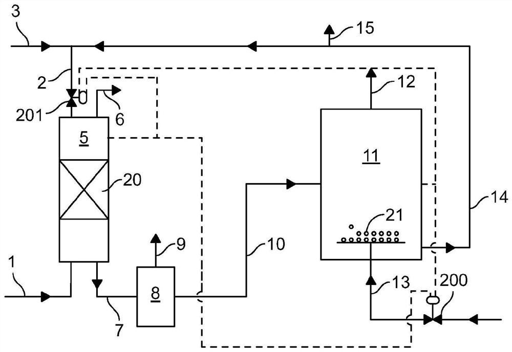
[0053] The following is based on figure 1 The description only presents one possible treatment method to achieve the object of the present invention, namely the removal of H from industrial fluid streams 2 S and produce useful thiosulfate products.

[0054] figure 1 A continuous process using absorber vessel 5 and oxidation reactor 11 operating in series is shown. Feed stream 1 (e.g., from 2 A feed consisting of natural gas of S) is fed to the bottom of the absorber 5 at a pressure of 30 bar gauge and directed in an upward flow for countercurrent contact with the liquid treatment solution 2 introduced at the top of the absorber 5 . Alternatively, the feed may be free of hydrocarbon components, for example, the feed may contain hydrogen sulfide and non-hydrogen gases. Such non-hydrogen gases can be air recovered from amine systems or CO recovered from sour water stripping processes 2 .

[0055] The absorber may contain solid media or may be a bubble column. Other feed...


PUM


Abstract

A process is presented where a feed stream containing a hydrogen sulfide and another feed component is introduced into an absorber that the feed stream flows upward from the bottom of the absorber andcontacts a liquid treatment solution, where the liquid treatment solution contains a sulfur dye catalyst. The hydrogen sulfide is absorbed into the liquid treatment solution and converted into sulfide ions. The other feed component is removed from the absorber vessel substantially free of the hydrogen sulfide and a spent treatment solution is also removed from the absorber vessel and fed to an oxidation vessel where it is contacted with an oxygen containing gas causing the sulfide ions to oxidize to thiosulfate and converting the spent sulfur dye catalyst to regenerated sulfur dye catalyst. The thiosulfate is recovered, and the regenerated sulfur dye catalyst can be recycled as part of the liquid treatment solution.

Description

[0001] Cross References to Related Applications [0002] This application claims priority to US Patent Application Serial No. 16 / 036,471, filed July 16, 2018, which is hereby incorporated by reference into this application. technical field [0003] The present disclosure relates to a method for the continuous removal of hydrogen sulfide gas (H 2 S) Process and apparatus and subsequent selective production of thiosulfate product. The method comprises absorbing H in the water treatment solution 2 S, followed by an oxidation reaction using a catalyst-containing vat dye to produce thiosulfate. The spent catalyst is regenerated using oxygen-containing gas in the oxidizer and recycled for use as part of the water treatment solution. Background technique [0004] It is known to remove sulfur pollutants, specifically H 2 S. Likewise, the removal of H from hydrocarbon-containing gas streams 2 S is known. However, such known methods for treating gas streams do not directly pro...

Claims


Application Information

Patent Timeline
IPC IPC(8): B01D53/14B01D53/52B01D53/86B01D53/96C10L3/10C01B17/64
CPCC01B17/64B01J38/70B01J38/12B01J38/64E21B43/34B01D53/1468B01D53/1418B01D53/1425B01D53/52B01D2252/10B01D2251/604B01D2251/606B01D2251/608B01D2257/304B01D2251/304B01D2251/306B01D2251/404C01B17/167C10L3/103C01B17/16B01D53/1412B01D53/8612B01D53/96B01D2251/2062B01D2255/70B01D2256/245C10L2290/10C10L2290/12C10L2290/541C10L2290/547C10L2290/58Y02P20/584E21B21/068E21B21/067B01D53/78B01D53/346B01D53/8693C02F2103/10C02F2103/18C02F2101/101B01D53/8603
Inventor D·杰克逊J·B·戈马赫M·哈迪
Owner MERICHEM CO
Why Eureka
Try Eureka