A real-time path planning method for laser selective melting based on temperature uniformity

A laser selective melting and real-time path planning technology, applied in the field of additive manufacturing, can solve problems such as real-time adjustment, temperature information lag, and large randomness, and achieve the effect of improving algorithm efficiency, improving calculation accuracy, and ensuring real-time response

Active Publication Date: 2021-12-03
HUAZHONG UNIV OF SCI & TECH
View PDF8 Cites 0 Cited by
  • Summary
  • Abstract
  • Description
  • Claims
  • Application Information

AI Technical Summary

Problems solved by technology

[0004] For the processing of large and complex parts, some scholars have found that the length of the scanning line in SLM forming has a great influence on the warpage deformation and residual stress of the part. The suitable range of the scanning line length is 5mm-10mm. Therefore, when processing large parts, it is necessary to The area division method of area scanning can effectively solve this problem; however, there are also related literatures that propose different dynamic path planning techniques or partition path planning: Concept Laser company proposes a partition random exposure strategy, which can solve the problem of heat accumulation to a certain extent, However, its randomness is relatively large; Qiang Xuhui et al. proposed a pseudo-random partition path strategy based on quadrant guidance, which can balance the temperature field distribution; AliAhrari et al. proposed a cell scanning strategy based on a multi-objective optimization method, which can reduce Part residual stress and deformation
The above partition scanning path planning generally considers the effect of the heat-affected zone, the cooling effect of the forming cavity, and the complexity of the algorithm and other influencing factors, which can reduce the local heat accumulation and residual stress of the part to a certain extent. It is set up before forming, and it is static relative to the printing process. It cannot be adjusted in real time during the forming process, and it is difficult to cope with different equipment working conditions and parts structure differences; for example, the patent of application number CN102962452B "Metal In "Laser Deposition Manufacturing Scanning Path Planning Method", the infrared thermal imager is used to directly measure the temperature of the laser deposition manufacturing layer, and based on the layer temperature distribution, the partition scanning path planning is realized, the temperature gradient and local thermal stress concentration are reduced, and the manufacturing quality is improved. The patent actually obtains the temperature distribution map of the layer after each layer is printed to plan the process parameters and scanning sequence of the next layer, and fails to adjust the printing strategy of the current layer in time, and its temperature information has a lag. Secondly, the patent is in Each layer is based on the temperature of each partition, and the scanning order of the partitions is optimized according to the principle of first low and then high. It fails to consider the changing law of the temperature distribution of each sub-region after printing, which will affect the scanning strategy. Therefore, this field urgently needs a A forming method capable of real-time path planning according to temperature changes in different regions in a single slice layer during processing

Method used


Image

  • A real-time path planning method for laser selective melting based on temperature uniformity
  • A real-time path planning method for laser selective melting based on temperature uniformity
  • A real-time path planning method for laser selective melting based on temperature uniformity

Examples


Embodiment Construction

[0031]In order to make the object, technical solution and advantages of the present invention clearer, the present invention will be further described in detail below in conjunction with the accompanying drawings and embodiments. It should be understood that the specific embodiments described here are only used to explain the present invention, not to limit the present invention. In addition, the technical features involved in the various embodiments of the present invention described below can be combined with each other as long as they do not constitute a conflict with each other.

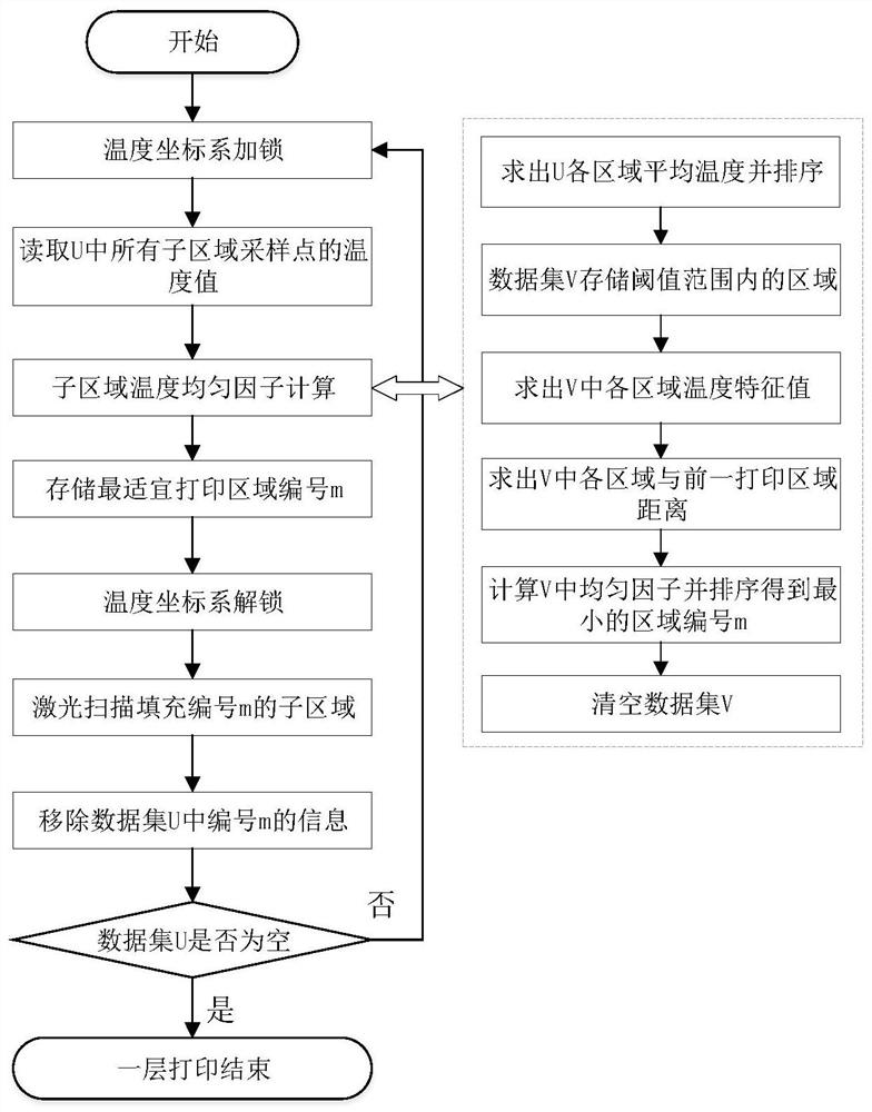
[0032] Such as figure 1 As shown, a real-time path planning method for laser selective melting based on temperature uniformity mainly includes the following steps:

[0033] Step 1: Study the change law of SLM temperature field and its influencing factors, and design the temperature uniformity factor.

[0034] (1) Filter all blocks to be printed. Prioritize printing in areas with lower average ...


PUM


Abstract

The invention belongs to the technical field related to additive manufacturing, and more specifically relates to a real-time path planning method for laser selective melting based on temperature uniformity. The method includes steps: S1, for a single slice layer to be formed, divide the slice layer to be formed into multiple regions, and select an initial forming region; S2, determine the next region to be formed in the following manner: measure each unformed The temperature of the forming area and the distance from the previous formed area, use the temperature and distance values ​​of each unformed area to construct the relational expression of the temperature uniformity factor, and calculate the temperature uniformity factor, and select the next one according to the temperature uniformity factor Shaping area; S3 Repeat step S2 until the shaping of all areas in the slice layer to be shaped is determined. Through the present invention, the real-time planning of the forming path is realized, the problem of thermal stress concentration caused by determining the next area to be formed solely based on temperature or distance is avoided, and the forming precision is high.

Description

technical field [0001] The invention belongs to the technical field related to additive manufacturing, and more specifically relates to a real-time path planning method for laser selective melting based on temperature uniformity. Background technique [0002] The working principle of SLM technology is to use the discrete layer profile information of the 3D model to control the high-energy laser beam to melt the metal powder layer by layer, and then layer by layer to obtain metal parts of any complex structure designed by the designer. The active area of ​​the high-energy laser beam is only the metal powder with the size of the spot. Under the action of the highly directional heat input and the fast heat source, the powder bed undergoes a rapid melting and solidification process locally, and a large temperature gradient and transient heat are generated in the spot area. stress. If the heat input cannot be effectively controlled during the forming process, the accumulation of...

Claims


Application Information

Patent Timeline
Patent Type & Authority Patents(China)
IPC IPC(8): B22F10/85B22F10/31B22F10/28B33Y10/00B33Y50/02
CPCB33Y10/00B33Y50/02
Inventor 张李超胡祺史玉升陈楠
Owner HUAZHONG UNIV OF SCI & TECH
Why Eureka
Try Eureka