Uniform segmenting and cutting equipment for supporting columns for obstetric and gynecological operation frames
A technology of cutting equipment and support column, which is applied to the field of evenly segmented cutting equipment for support columns used in obstetrics and gynecology operating frames, can solve the problems of low work efficiency, difficulty in keeping the same length of sanitary stainless steel pipes, etc., and achieve automatic cutting and automatic collection. , the incision is flat, the effect of convenient work
- Summary
- Abstract
- Description
- Claims
- Application Information
AI Technical Summary
Problems solved by technology
Method used
Image
Examples
Embodiment 1
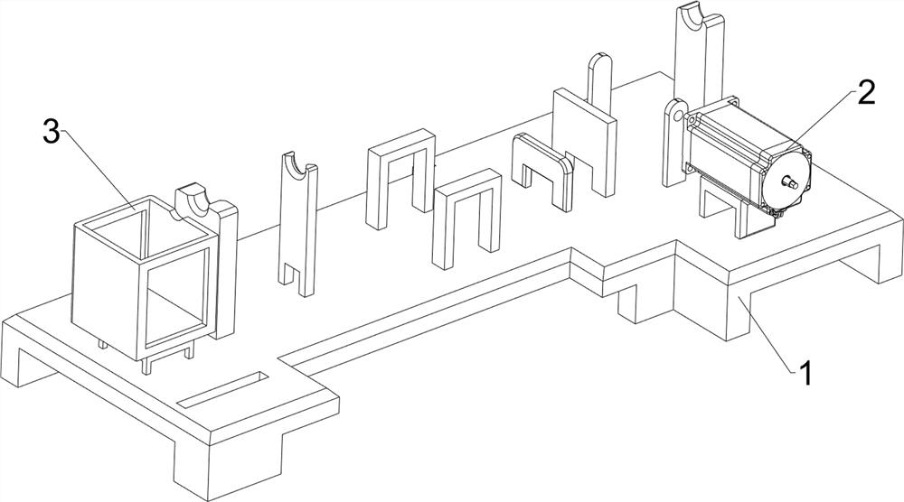
[0080] A support column for obstetrics and gynecology surgical frame evenly segmented cutting equipment, such as figure 1 and figure 2 As shown, it includes a bottom plate 1, a servo motor 2, a first collection box 3, a moving mechanism 4, a cutting mechanism 5, a guiding mechanism 6 and a clamping mechanism 7. The servo motor 2 is provided on the front right of the top of the bottom plate 1, and the bottom plate 1 There is a first collection box 3 in the middle on the left side of the top, a moving mechanism 4 is arranged between the top rear side of the bottom plate 1 and the output shaft of the servo motor 2, a cutting mechanism 5 is arranged between the top rear side of the bottom plate 1 and the moving mechanism 4, and the bottom plate 1 A guide mechanism 6 is provided on the left side of the top, and the guide mechanism 6 is located on the right side of the first collection box 3 .
[0081] When people need to cut the sanitary grade stainless steel pipe, first put the ...
Embodiment 2
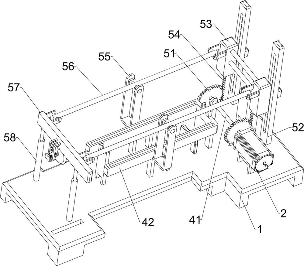
[0083] On the basis of Example 1, such as image 3 , Figure 4 , Figure 5 , Figure 6 and Figure 7 As shown, the moving mechanism 4 includes a first rotating shaft 41, a first mounting plate 42, a reel 43, a first slider 44, a second slider 45, a pull cord 46, a first spring 47, a second rotating shaft 48 and Elastic clip 49, the upper part of the rear right side of the base plate 1 is rotatably provided with a first rotating shaft 41, the front end of the first rotating shaft 41 is connected with the output shaft of the servo motor 2, and the first mounting plate 42 is arranged in the middle of the top of the base plate 1, the first rotating shaft 41 middle part is provided with reel 43, and the first mounting plate 42 upper sliding type is provided with first slide block 44 and second slide block 45, and second slide block 45 is positioned at the left side of first slide block 44, and on reel 43 A stay cord 46 is wound around, and the two ends of the stay cord 46 are r...
Embodiment 3
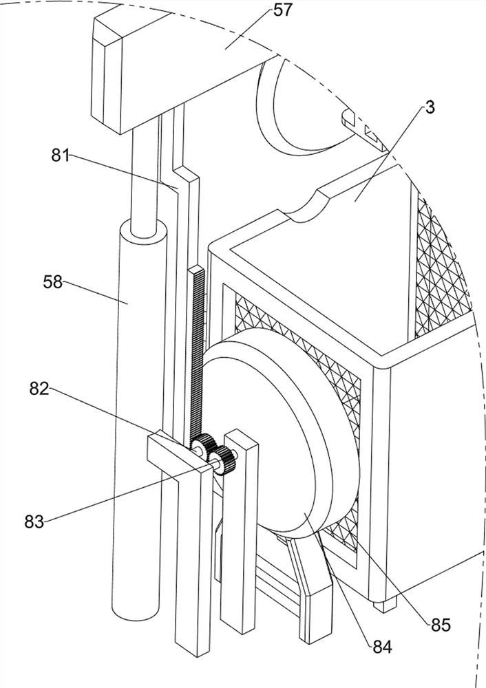
[0092] On the basis of Example 2, such as Figure 8 , Figure 9 and Figure 10 Shown, also comprise chip removal mechanism 8, chip removal mechanism 8 includes second rack 81, the 4th rotating shaft 82, the 2nd spur gear 83, fan 84 and barbed wire 85, electric cutter 57 bottom rear sides are provided with second Rack 81, the left and right sides of base plate 1 left rear side top are all rotatably provided with the 4th rotating shaft 82, are provided with the 2nd spur gear 83 on the 4th rotating shaft 82, the 2nd spur gear 83 meshes with each other, the 4th rotating shaft 82 on the right side Two spur gears 83 mesh with the second rack 81. A fan 84 is provided at the left rear portion of the top of the base plate 1. The fan blade rear portion in the fan 84 is connected with the front end of the fourth rotating shaft 82 on the left side. The front and rear of the first collection box 3 Both sides are provided with barbed wire 85.
[0093]When the electric cutter 57 moves dow...
PUM
 Abstract
Description
Claims
Application Information
 - R&D
- Intellectual Property
- Life Sciences
- Materials
- Tech Scout
- Unparalleled Data Quality
- Higher Quality Content
- 60% Fewer Hallucinations
Browse by: Latest US Patents, China's latest patents, Technical Efficacy Thesaurus, Application Domain, Technology Topic, Popular Technical Reports.
© 2025 PatSnap. All rights reserved.Legal|Privacy policy|Modern Slavery Act Transparency Statement|Sitemap|About US| Contact US: help@patsnap.com


