PWM constant-current double-feedback laser driving circuit
A drive circuit, constant current drive technology, applied in the direction of lasers, laser components, semiconductor lasers, etc., can solve the problems that cannot meet the system application
- Summary
- Abstract
- Description
- Claims
- Application Information
AI Technical Summary
Problems solved by technology
Method used
Image
Examples
Embodiment 1
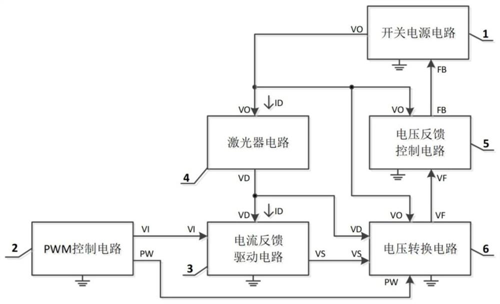
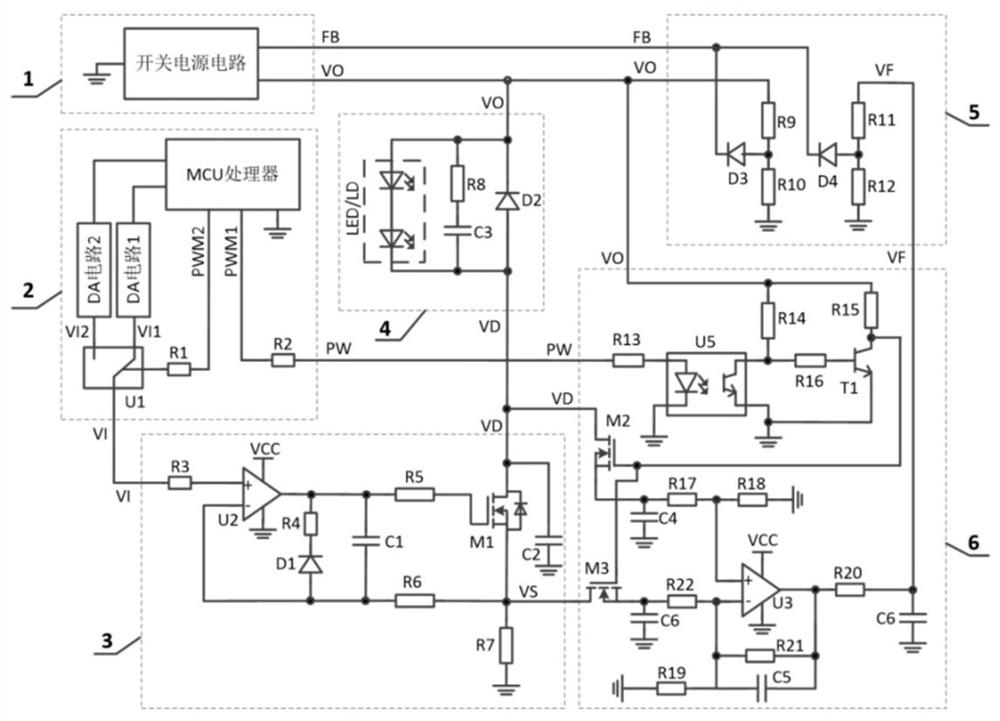
[0148] Such as figure 1 and figure 2 As shown in FIG. 1 , they are respectively a circuit implementation block diagram of the embodiment of the present invention and a detailed schematic diagram of the circuit implementation of the embodiment of the present invention. figure 1 The realization block diagram shown includes: a switching power supply circuit, a PWM control circuit, a current feedback drive circuit, a laser circuit, a voltage feedback control circuit, and a voltage conversion circuit.
[0149] The specific implementation details are as figure 2 Shown:
[0150] The output voltage VO of the switching power supply circuit is provided to the laser circuit and the voltage conversion circuit as power supply, VO is provided to the voltage feedback control circuit for setting the overvoltage protection point, and the output signal FB of the voltage feedback control circuit is provided to the switching power supply circuit for control The size of the output voltage;
...
Embodiment 2
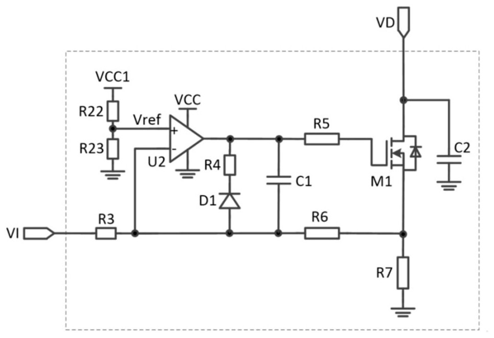
[0157] Such as image 3 As shown, it is a second implementation circuit diagram of the current feedback and driving circuit described in the embodiment of the present invention. The realization block diagram of the PWM constant current driving circuit of the double feedback control of the present embodiment is as follows figure 1 As mentioned above, the difference with Embodiment 1 is that the current feedback circuit adopts image 3 the scheme shown;
[0158] image 3 The current feedback circuit constitutes a current parallel deep negative feedback circuit; the voltage input signal VI is connected to the PWM control circuit to control the magnitude of the output current, and the calculation of the output current is shown in formula 2; the voltage signal VD is connected to the laser circuit, and the depth The negative feedback circuit controls the MOS transistor M1 to work in the linear constant current region to realize the constant current output control of the entire ci...
Embodiment 3
[0160] Such as Figure 4 As shown, it is a second implementation circuit diagram of the PWM control circuit described in the embodiment of the present invention. The realization block diagram of the PWM constant current driving circuit of the double feedback control of the present embodiment is as follows figure 1 As mentioned above, the difference from Embodiment 1 is that the PWM control circuit adopts Figure 4 the scheme shown;
[0161] Figure 4 The PWM control circuit in the figure 2 The difference in the PWM control circuit is that figure 2 The DA conversion circuit in 2 uses Figure 5 The voltage division of the resistor R26 and the resistor R27 is replaced, and the other parts are the same as in Embodiment 1.
[0162] The settings of resistors R26 and R27 are as follows: for the current feedback driving circuit in the circuit diagram in embodiment 1, the current series negative feedback is adopted, at this time, R26 adopts a resistance value above 4.7kΩ or doe...
PUM
 Abstract
Description
Claims
Application Information
 - R&D
- Intellectual Property
- Life Sciences
- Materials
- Tech Scout
- Unparalleled Data Quality
- Higher Quality Content
- 60% Fewer Hallucinations
Browse by: Latest US Patents, China's latest patents, Technical Efficacy Thesaurus, Application Domain, Technology Topic, Popular Technical Reports.
© 2025 PatSnap. All rights reserved.Legal|Privacy policy|Modern Slavery Act Transparency Statement|Sitemap|About US| Contact US: help@patsnap.com


