
A pwm constant current double feedback laser drive circuit

A technology of drive circuit and negative feedback circuit, which is applied in the field of constant current laser drive circuit, can solve the problems that cannot satisfy the system application, and achieve the effect of high precision, good stability and high stability

Active Publication Date: 2021-05-25
CASI VISION TECH (BEIJING) CO LTD +1
View PDF0 Cites 0 Cited by
  • Summary
  • Abstract
  • Description
  • Claims
  • Application Information

AI Technical Summary

Problems solved by technology

[0007] Therefore, the high-power LD laser current is required to be as high as 40A or above, and its pulse width and strobe are required to be PWM adjusted according to the feedback parameters. The existing solutions can no longer meet the application of these systems.

Method used


Image

  • A pwm constant current double feedback laser drive circuit
  • A pwm constant current double feedback laser drive circuit
  • A pwm constant current double feedback laser drive circuit

Examples


Embodiment 1

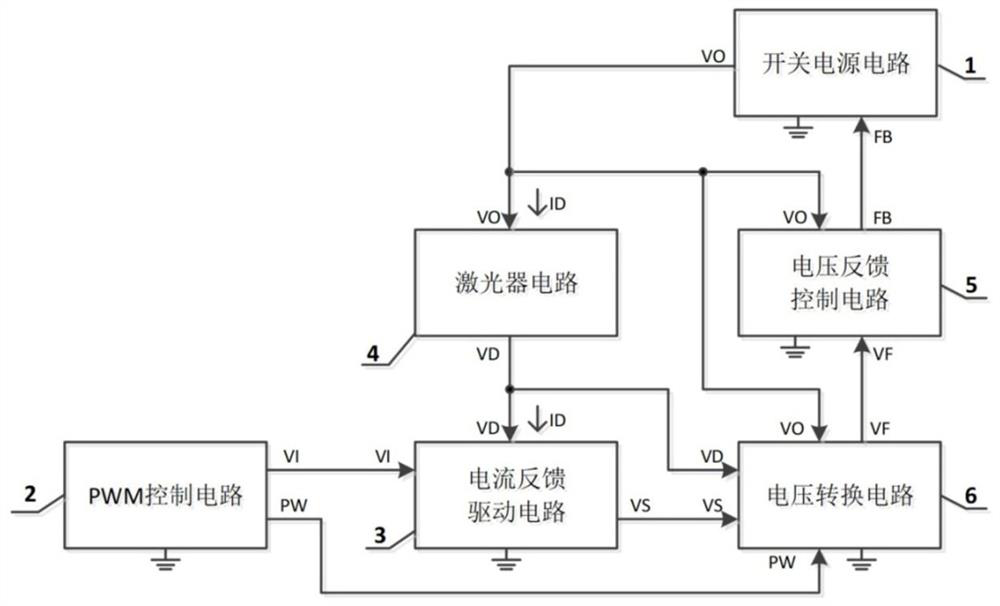
[0148] Such as figure 1 with figure 2 As shown in FIG. 1 , they are respectively a circuit implementation block diagram of the embodiment of the present invention and a detailed schematic diagram of the circuit implementation of the embodiment of the present invention. figure 1 The realization block diagram shown includes: a switching power supply circuit, a PWM control circuit, a current feedback drive circuit, a laser circuit, a voltage feedback control circuit, and a voltage conversion circuit.

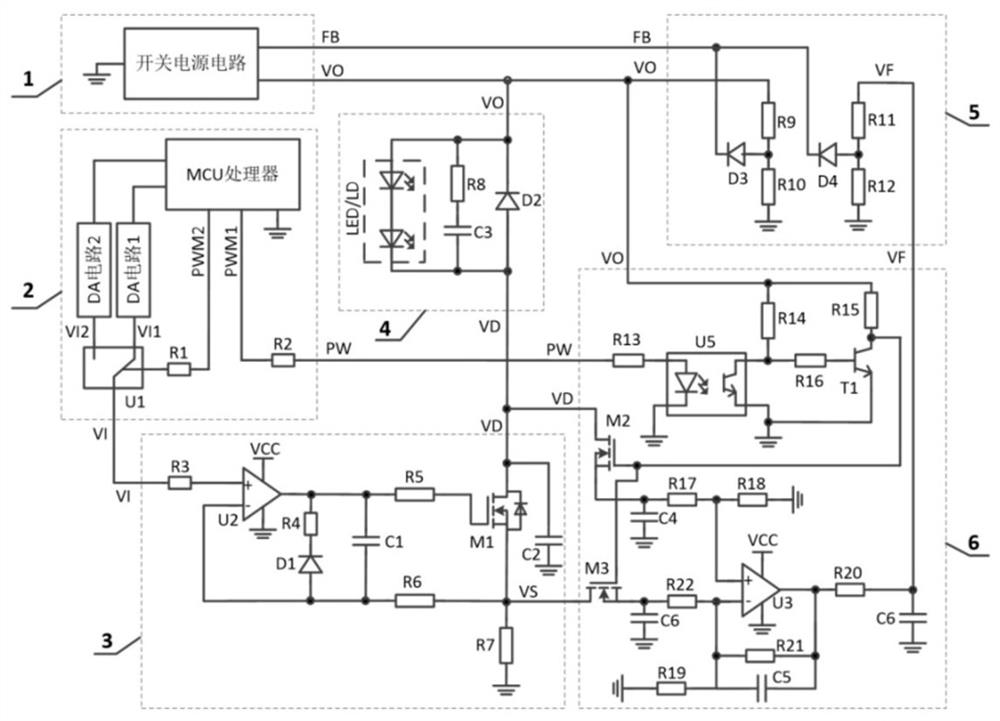
[0149] The specific implementation details are as figure 2 Shown:

[0150] The output voltage VO of the switching power supply circuit is provided to the laser circuit and the voltage conversion circuit as power supply, VO is provided to the voltage feedback control circuit for setting the overvoltage protection point, and the output signal FB of the voltage feedback control circuit is provided to the switching power supply circuit for control The size of the output voltage; ...

Embodiment 2

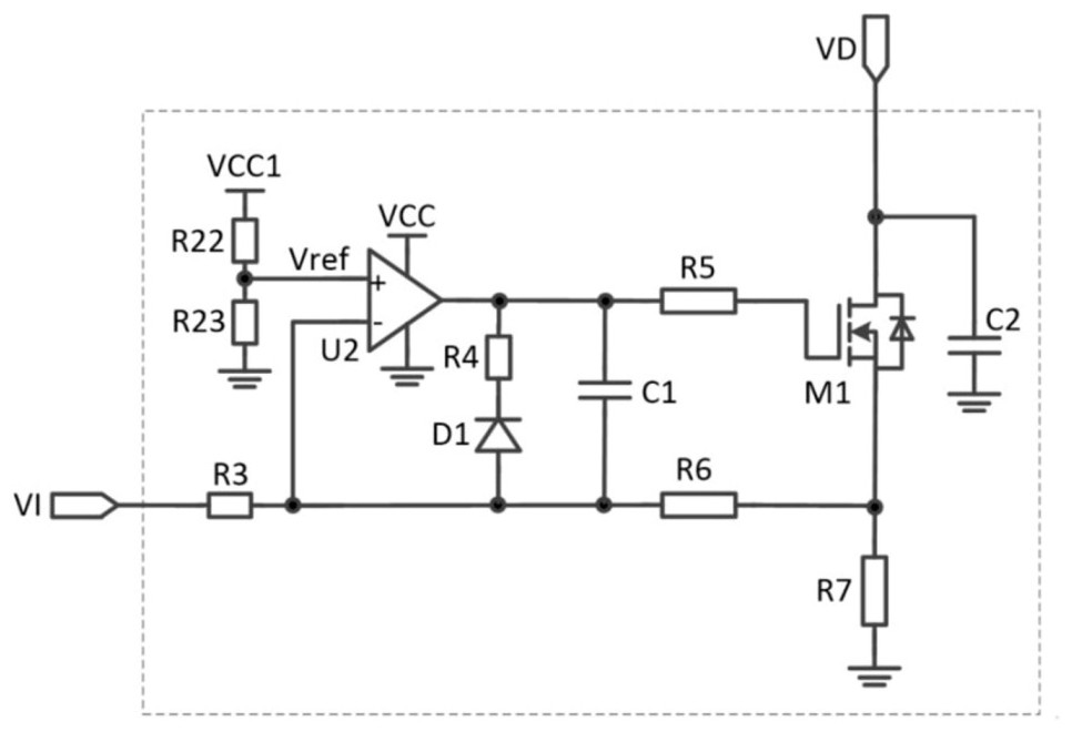
[0157] Such as image 3 As shown, it is a second implementation circuit diagram of the current feedback and driving circuit described in the embodiment of the present invention. The realization block diagram of the PWM constant current driving circuit of the double feedback control of the present embodiment is as follows figure 1 As mentioned above, the difference with Embodiment 1 is that the current feedback circuit adopts image 3 the scheme shown;

[0158] image 3 The current feedback circuit constitutes a current parallel deep negative feedback circuit; the voltage input signal VI is connected to the PWM control circuit to control the magnitude of the output current, and the calculation of the output current is shown in formula 2; the voltage signal VD is connected to the laser circuit, and the depth The negative feedback circuit controls the MOS transistor M1 to work in the linear constant current region to realize the constant current output control of the entire ci...

Embodiment 3

[0160] Such as Figure 4 As shown, it is a second implementation circuit diagram of the PWM control circuit described in the embodiment of the present invention. The realization block diagram of the PWM constant current driving circuit of the double feedback control of the present embodiment is as follows figure 1 As mentioned above, the difference from Embodiment 1 is that the PWM control circuit adopts Figure 4 the scheme shown;

[0161] Figure 4 The PWM control circuit in the figure 2 The difference in the PWM control circuit is that figure 2 The DA conversion circuit in 2 uses Figure 5 The voltage division of the resistor R26 and the resistor R27 is replaced, and the other parts are the same as in Embodiment 1.

[0162] The settings of resistors R26 and R27 are as follows: for the current feedback driving circuit in the circuit diagram in embodiment 1, the current series negative feedback is adopted, at this time, R26 adopts a resistance value above 4.7kΩ or doe...


PUM


Abstract

The present application discloses a PWM constant current dual feedback laser drive circuit, including a switching power supply circuit, a PWM control circuit, a current feedback drive circuit, a laser circuit, a voltage feedback control circuit and a voltage conversion circuit. The switching power supply circuit is used for receiving the feedback signal FB output by the voltage feedback control circuit; the current feedback driving circuit is used for receiving the voltage signal VI of the PWM control circuit, and controls the current ID flowing through the laser circuit, providing The voltage signal VD and the voltage signal VS are given to the voltage conversion circuit. The invention realizes high-precision and high-stability constant current or PWM constant current output when the high-power laser is driven, and can adaptively adjust the output voltage of the adjustable switching power supply according to the working voltage of the laser and the voltage drop of the power tube in the current feedback circuit , which improves the working efficiency of the system.

Description

technical field [0001] The invention relates to the technical field of laser circuits, in particular to a constant-current laser driving circuit and a control method with double feedback of voltage and current and PWM control. Background technique [0002] Semiconductor lasers, also known as laser diodes (English full name Laser diode, LD), are currently widely used in laser ranging, laser marking, laser radar, laser communication, laser simulation weapons, photoelectric information processing, medical military, testing instruments, etc. . [0003] Semiconductor lasers work by direct injection of carriers, and the stability of the injection current has a direct and obvious impact on the output of the laser. Therefore, the driving technology of semiconductor lasers usually adopts a constant current drive method, which usually requires high output current stability. The surge current is small and the ripple is small. [0004] With the development of laser technology, the out...

Claims


Application Information

Patent Timeline
Patent Type & Authority Patents(China)
IPC IPC(8): H02M1/00H01S5/042H01S5/068
CPCH02M1/00H01S5/042H01S5/0427H01S5/0428
Inventor 胡肖松骈冰戢冰张武杰
Owner CASI VISION TECH (BEIJING) CO LTD
Learn More