Vertical type linear cutting machine tool and using method thereof
A wire-cutting machine tool and vertical technology, which is used in electric machining equipment, electrode manufacturing, accessories, etc., can solve problems such as affecting workpiece cutting, easy wire softening, and jittering.
- Summary
- Abstract
- Description
- Claims
- Application Information
AI Technical Summary
Problems solved by technology
Method used
Image
Examples
Embodiment 1
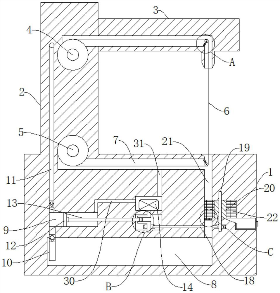
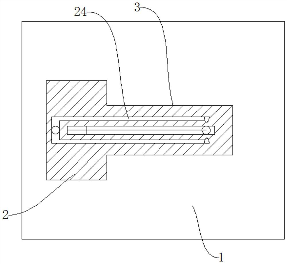
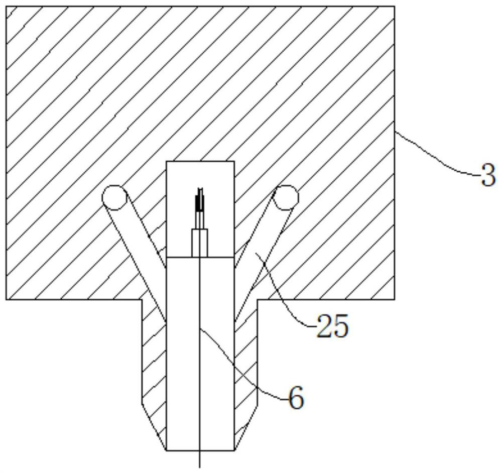
[0041] refer to Figure 1-7 , a vertical wire cutting machine tool, comprising a base 1, a support column 2 is fixedly connected to one side of the upper end of the base 1, a cross bar 3 is fixedly connected to the upper end of the support column 2, and a pay-off wheel 4 is connected to the support column 2 for symmetrical rotation. The wire wheel 5, the base 1, and the cross bar 3 are all provided with a wire slot 7, and the wire slot 7 is connected with a wire 6, and the two ends of the wire 6 are connected with the pay-off wheel 4 and the take-up wheel 5 respectively, Fixedly connected with a fixed tube 27, the fixed tube 27 is slidingly connected with a telescopic rod 28, the telescopic rod 28 is sleeved with a return spring 29, and the two ends of the back spring 29 are fixedly connected with the telescopic rod 28 and the fixed tube 27 respectively, and the telescopic rod 28 is away from the One end of the fixed cylinder 27 is connected with a reversing wheel 26 in rotati...
Embodiment 2
[0048] refer to figure 1 , a vertical wire cutting machine tool, which is basically the same as Embodiment 1, furthermore: the base 1 is provided with a placement groove, the placement groove is connected with a driving motor 14, and the output end of the driving motor 14 is connected with a rotating main shaft 15, which is convenient Drive the unit.
Embodiment 3
[0050] refer to figure 1 , Figure 5 , a vertical wire cutting machine tool, which is basically the same as that of Embodiment 1, furthermore: a liquid suction chamber 9 is provided at the lower end of the base 1, and a push plate 12 is slidably connected in the liquid suction chamber 9, and one side of the push plate 12 is rotationally connected Connecting rod 13 is arranged, and crankshaft 16 is fixedly connected on the rotating main shaft 15, and one end of connecting rod 13 away from crankshaft 16 is rotationally connected with crankshaft 16, is convenient to make push plate 12 carry out reciprocating motion.
PUM
 Abstract
Description
Claims
Application Information
 - R&D
- Intellectual Property
- Life Sciences
- Materials
- Tech Scout
- Unparalleled Data Quality
- Higher Quality Content
- 60% Fewer Hallucinations
Browse by: Latest US Patents, China's latest patents, Technical Efficacy Thesaurus, Application Domain, Technology Topic, Popular Technical Reports.
© 2025 PatSnap. All rights reserved.Legal|Privacy policy|Modern Slavery Act Transparency Statement|Sitemap|About US| Contact US: help@patsnap.com


