
Temporary gas barrier type spontaneous combustion prevention solar photovoltaic panel

A solar photovoltaic panel and gas barrier technology, applied in the field of solar photovoltaic panels, can solve problems such as low fire extinguishing efficiency, solar photovoltaic panel damage, economic damage, etc., and achieve high-efficiency fire extinguishing protection treatment, fast and accurate fire extinguishing treatment, and reduce escape speed Effect

Inactive Publication Date: 2021-03-09
陈萍
View PDF0 Cites 0 Cited by
  • Summary
  • Abstract
  • Description
  • Claims
  • Application Information

AI Technical Summary

Problems solved by technology

[0007] The purpose of the present invention is to provide a temporary gas barrier type anti-spontaneous combustion solar photovoltaic panel to solve the above-mentioned background technology. The existing solar photovoltaic panels are easy to be damaged due to short-circuiting of local zero devices in the internal circuit, resulting in large-area photovoltaic panels. The continuous heating and burning of the panels leads to the complete damage of the solar photovoltaic panels used in the overall assembly, resulting in serious damage to the economy and safety hazards in use. There are defects in use, and the overall isolated fire extinguishing cannot be carried out when the spontaneous combustion of the solar photovoltaic panels begins. Dealing with protection will easily lead to implicated damage to other photovoltaic panels and low fire extinguishing efficiency

Method used


Image

  • Temporary gas barrier type spontaneous combustion prevention solar photovoltaic panel
  • Temporary gas barrier type spontaneous combustion prevention solar photovoltaic panel
  • Temporary gas barrier type spontaneous combustion prevention solar photovoltaic panel

Examples


Embodiment Construction

[0030] The following will clearly and completely describe the technical solutions in the embodiments of the present invention with reference to the accompanying drawings in the embodiments of the present invention. Obviously, the described embodiments are only some, not all, embodiments of the present invention. Based on the embodiments of the present invention, all other embodiments obtained by persons of ordinary skill in the art without making creative efforts belong to the protection scope of the present invention.

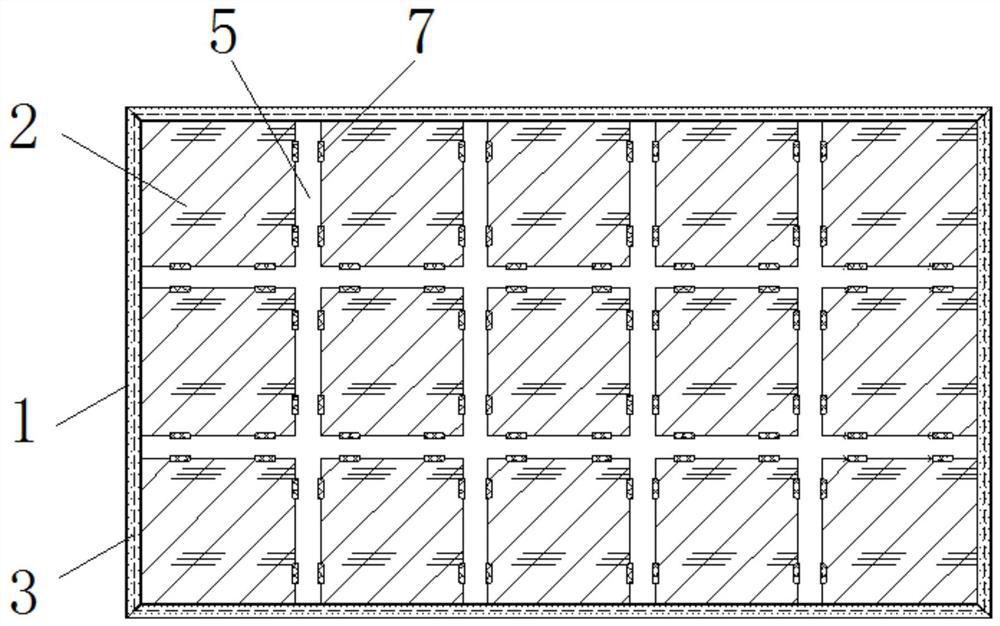
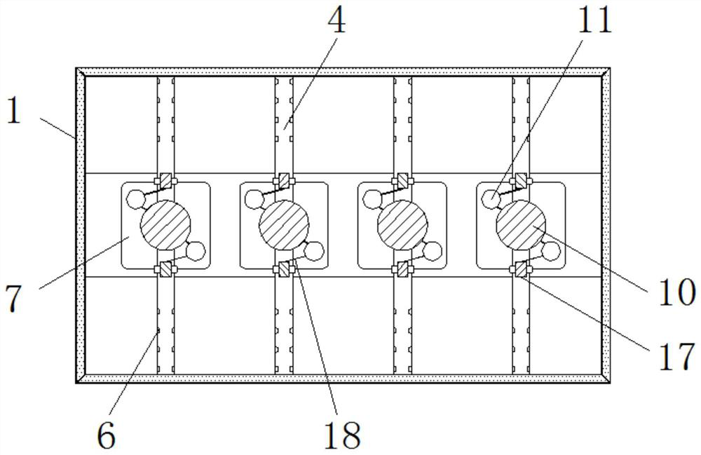
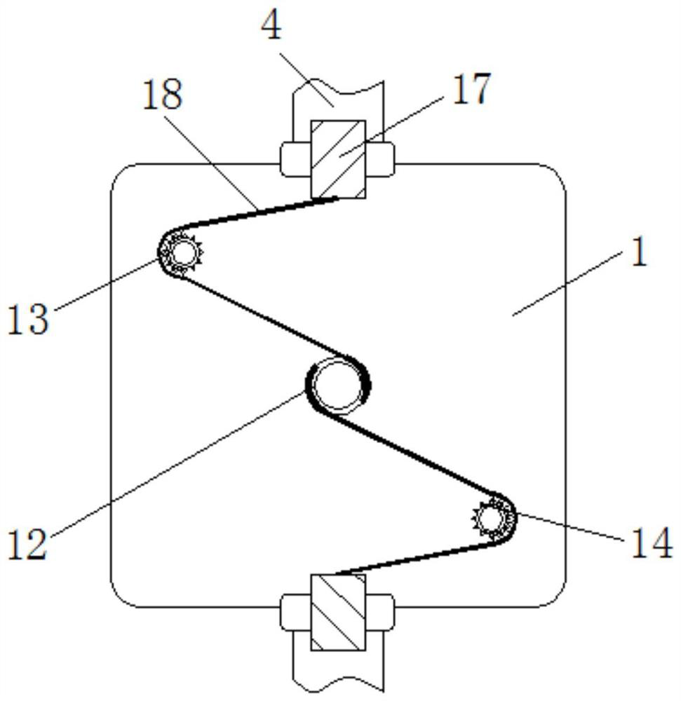
[0031] see Figure 1-9 , the present invention provides a technical solution: a temporary gas barrier anti-spontaneous combustion solar photovoltaic panel, including an outer frame 1, a photovoltaic panel body 2, a return tank 3, a first ventilation pipe 4, a second ventilation pipe 5, air holes 6, Rubber sheet 7, sealed air cavity 8, net bag 9, reaction tank 10, compressed gas tank 11, first casing 12, second casing 13, gear ring 14, sealing plate 15, ventila...


PUM


Abstract

The invention discloses a temporary gas barrier type spontaneous combustion prevention solar photovoltaic panel. The temporary gas barrier type spontaneous combustion prevention solar photovoltaic panel comprises an outer frame, a photovoltaic panel body, a reaction tank, compressed gas tanks and a vent valve shaft, wherein the photovoltaic panel body is embedded in the top of the outer frame, andbackflow grooves are formed in the edges of the top and the bottom of the outer frame; a first ventilation pipe and a second ventilation pipe are connected in a penetrating mode, air holes are formedin the outer walls of the first ventilation pipe and the second ventilation pipe, rubber sheets are movably mounted on the outer sides of the air holes in the second ventilation pipe in an embedded mode, and a sealing air cavity is formed in the middle of the first ventilation pipe at the bottom of the outer frame; and a net bag is fixed at the bottom of the outer frame in the sealing air cavity.According to the temporary gas barrier type spontaneous combustion prevention solar photovoltaic panel, oxygen can be rapidly isolated when the photovoltaic panel spontaneously combusts, conditions required by spontaneous combustion are completely eradicated through generation of carbon dioxide gas, and efficient fire extinguishing protection treatment of the photovoltaic panel is achieved.

Description

technical field [0001] The invention relates to the technical field of solar photovoltaic panels, in particular to a temporary gas barrier anti-spontaneous combustion solar photovoltaic panel. Background technique [0002] Solar photovoltaic panels are components that convert and utilize solar energy. Through long-term solar irradiation, solar energy is converted into electrical energy and stored, and used outdoors and in areas where industrial plants are located. After one installation, it can effectively generate sustainable energy for a long time. Regenerated electric energy is an important part of the existing clean and sustainable utilization of renewable resources, and it provides continuous electric energy supply for remote environmental areas where remote electric energy transmission is inconvenient, and improves the full utilization efficiency of solar energy. [0003] However, the existing solar photovoltaic panels have the following problems in use: [0004] 1. I...

Claims


Application Information

Patent Timeline
IPC IPC(8): A62C3/16A62C99/00
CPCA62C3/16A62C99/0027
Inventor 不公告发明人
Owner 陈萍
Learn More