A fluid pipeline cleaning device and a cleaning method using the cleaning device

A technology for cleaning devices and fluid pipelines, applied in the direction of cleaning methods using liquids, cleaning methods and utensils, measuring devices, etc., can solve the problem of efficient and fast cleaning of pipelines that are difficult to adapt to large quantities, and difficult to adapt to a variety of different Cleaned pipelines, fluid pipeline interface damage and other problems, to achieve the effect of improving cleaning efficiency and cleaning ability, improving cleaning ability, and avoiding chemical corrosion

Active Publication Date: 2022-03-25
潍坊嘉腾液压技术有限公司
View PDF0 Cites 0 Cited by
  • Summary
  • Abstract
  • Description
  • Claims
  • Application Information

AI Technical Summary

Problems solved by technology

In practice, limited by space and design, traditional fluid pipeline cleaning devices are difficult to adapt to a variety of different pipelines to be cleaned, and the time to connect and disassemble the pipeline to be cleaned is almost the same as the pipeline cleaning time. It is difficult to adapt to the efficient and fast cleaning of a large number of pipelines; in addition, after repeated use, it will cause irreparable damage to the interface of the fluid pipeline

Method used


Image

  • A fluid pipeline cleaning device and a cleaning method using the cleaning device
  • A fluid pipeline cleaning device and a cleaning method using the cleaning device
  • A fluid pipeline cleaning device and a cleaning method using the cleaning device

Examples


Embodiment approach

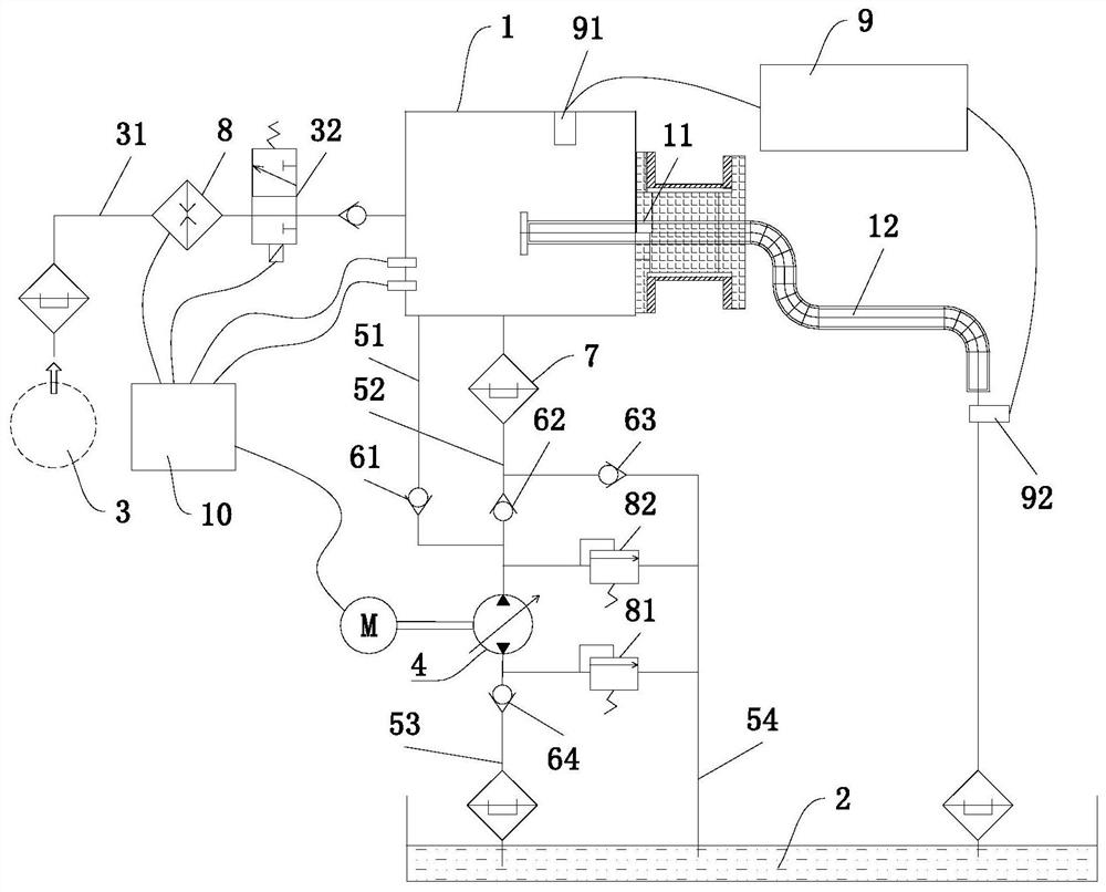
[0085] As a variable embodiment in the present embodiment, the set of pneumatic cavity 1 can be selectively enabled to generate a negative pressure generating device internally generating a negative pressure energy in the center. The fluid cleaning solution is refluxed in the cleaning line. The negative pressure generating device selectively selects a pressure relief member or apparatus having a pressure relief function, for example, a piston cylinder having a suction function or the like. In this embodiment, the liquid pump 4 can be made to the piston cylinder of the suction function, and the manufacturing cost can be effectively reduced.

[0086] As a preferred embodiment of the present application, the airflow control switch 32 is further selectively provided on the gas passage 31, and the gas flow control switch 32 controls the gas working source 3 and the collector body 1. The airflow is turned off; the airflow control switch 32 can be further set to a manual switch or an ele...


PUM


Abstract

The present application discloses a fluid pipeline cleaning device, which includes a collecting chamber provided with an installation interface, a gas working medium source for providing gaseous cleaning working fluid, and a liquid working medium source for providing liquid cleaning working fluid. The installation interface is in sealing connection with the collecting cavity; the gas working medium source communicates with the collecting cavity through a gas pipeline, and the liquid working medium source communicates with the collecting cavity through a liquid flow channel provided with a liquid pump. The collecting cavity is connected, and the liquid working medium source can provide liquid cleaning working medium to the pipeline to be cleaned through the collecting cavity; the liquid cleaning working medium has a forward cleaning state and a reverse cleaning state. The invention also discloses a cleaning method using the cleaning device. The cleaning device and cleaning method disclosed in this application have the advantages of high cleaning efficiency, high degree of intelligence, scientific cleaning strategy, and can meet the cleaning of various types of pipelines, and the cleaning device also has good responsiveness and long service life. Long, safe and reliable system and other advantages.

Description

Technical field [0001] The present application belongs to the field of fluid dynamics and line cleaning, and more particularly to a fluid line cleaning device and a cleaning method of using the cleaning device. Background technique [0002] In the field of fluid dynamics, especially hydraulic, air pressure, etc. Requirements, and new requirements for the degree of cleaning of the fluid line. Thereby, the apparatus for cleaning the stainless fluid pipeline will be delivered. [0003] At present, the cleaning method of fluid lines mainly has the following, such as ultrasonic cleaning, wire brush cleaning, oil or chemical solvent cleaning, high pressure water jet rinsing or airflow purity. Among them, the ultrasonic cleaning is good for the cleaning effect of the inner wall of the straight tube, but the cleaning effect of the inner wall of the bending line is not ideal; when the oil or chemical solvent is cleaned, the oil is residually residue or Chemical residues, will also cause p...

Claims


Application Information

Patent Timeline
Patent Type & Authority Patents(China)
IPC IPC(8): B08B9/032B08B3/14F26B21/00F17D1/14F17D3/01F17D5/00G01N15/10
CPCB08B9/032B08B3/14F26B21/001F17D1/14F17D3/01F17D5/00G01N15/10
Inventor 黄爱武王洪涛
Owner 潍坊嘉腾液压技术有限公司
Why Eureka
Try Eureka