Staggered edge drill reamer for composite hole machining

A composite material and hole processing technology, which is applied in the direction of reamers, manufacturing tools, drilling accessories, etc., can solve the problems of poor mirror processing effect, etc., and achieve the effect of improving chip removal, easy installation and disassembly, dense and hard metal surface structure

Active Publication Date: 2021-03-09
河源市蓝海米克模具刀具有限公司
View PDF13 Cites 4 Cited by
  • Summary
  • Abstract
  • Description
  • Claims
  • Application Information

AI Technical Summary

Problems solved by technology

[0005] To this end, the present invention provides a composite material hole machining staggered edge drill reamer, the chips generated by the secondary cutting edge and the arc edge on the metal processing surface are diverted to the chip guide groove through the chip splitting groove, and the chips of the main cutting edge go to the chip guide g

Method used


Image

  • Staggered edge drill reamer for composite hole machining
  • Staggered edge drill reamer for composite hole machining
  • Staggered edge drill reamer for composite hole machining

Examples


Embodiment 1

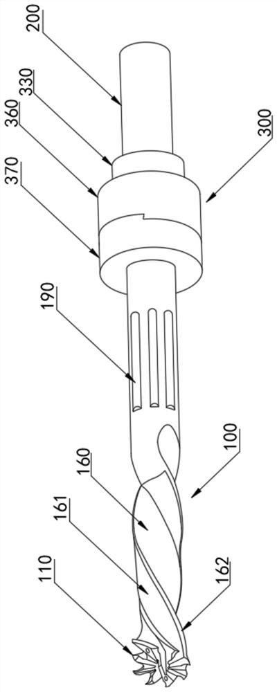
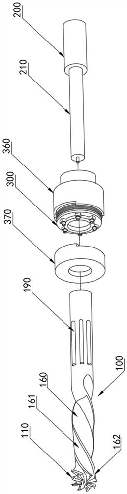
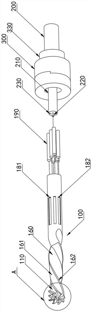
[0039] Embodiment 1, with reference to attached Figure 1-14 , a composite material hole processing staggered edge drill reamer provided by the present invention includes a drill rod 100, a tail handle 200 and an adjustment device 300, the right end of the drill rod 100 is provided with an adjustment device 300, and the adjustment device 300 includes a shell one 310, specifically , a parallel bearing 312 is fixedly installed on the left side of the first shell 310, a second shell 320 is fixedly installed on the left side of the parallel bearing 312, a limit ring 330 is fixedly installed on the right side of the first shell 310, and a tail handle 200 is fixedly installed on the right side of the limit ring 330, The mandrel 210 is fixedly installed on the left side of the tail handle 200, and the mandrel 210 is installed on the inner wall of the shell 1 310 and the shell 2 320, and the left side of the shell 2 320 is provided with a through hole 1 324, and the adjustment device 3...

Embodiment 2

[0052] Refer to the attached Figure 15 , a composite material hole processing staggered edge drill reamer in this embodiment also includes a limit frame 184;

[0053] Further, the limit frame 184 is fixedly installed on the inner wall of the installation groove 181, and the roller 190 is movably installed on the inner wall of the limit frame 184. Specifically, the limit frame 184 is set in a cage shape, and the roller 190 can be installed on the limit frame 184 inner wall first. , the limit frame 184 is installed on the inner wall of the installation groove 181, and the limit frame 184 has the function of facilitating the installation of the roller 190. The limit frame 184 is made of Teflon, and Teflon uses fluorine to replace all polyethylene. The artificially synthesized polymer material of hydrogen atoms, polytetrafluoroethylene has the characteristics of high temperature resistance, extremely low friction coefficient, good wear resistance and excellent chemical stability,...


PUM


Abstract

The invention belongs to the technical field of industrial tools, and particularly relates to a staggered edge drill reamer for composite hole machining. The staggered edge drill reamer comprises a drill rod, a tail handle and an adjusting device. According to the technical scheme, the adjusting device is arranged at the right end of the drill rod, and comprises a shell I, and a parallel bearing is fixedly mounted on the left side of the shell I; a shell II is fixedly installed on the left side of the parallel bearing, and a spacing ring is fixedly installed on the right side of the shell I; and the tail handle is fixedly installed on the right side of the spacing ring, and a mandrel is fixedly arranged on the left side of the tail handle, and installed on the inner walls of the shell I and the shell II. The invention has the beneficial effects that chips generated on a metal processing surface through ab auxiliary cutting edge and an arc edge are guided to a chip guide groove througha chip dividing groove, and the chips of a main cutting edge are guided to a chip groove through the chip guide groove; a roller is attached to the metal surface in the hole, and the metal surface inthe hole is rolled through the roller, so that the protrusion part of the surface is pressed into the concave part; and the smooth surface is machined in the hole, and the super mirror machining and polishing effects are achieved.

Description

technical field [0001] The invention relates to the technical field of industrial cutting tools, in particular to a drilling and reaming tool with staggered edges for machining holes made of composite materials. Background technique [0002] The drill reamer has one or more cutter teeth, which are used to remove the thin metal layer on the machined surface of the hole. The hole processed by the reamer can obtain accurate size and shape. The reamer is used to ream the drilled workpiece The hole after cutting or reaming is mainly to improve the machining accuracy of the hole and reduce the roughness of its surface. It is a tool for finishing and semi-finishing the hole. The machining allowance is generally small, and it is used to process the cylinder. Reamers for shaped holes are more commonly used. [0003] The existing technology has the following disadvantages: the existing tools can only be used for fine cutting of non-ferrous metals and non-metals, and are prone to defe...

Claims


Application Information

Patent Timeline
IPC IPC(8): B23B51/08B23D77/00
CPCB23B51/08B23D77/00
Inventor 凌喜乐林鹏杨勇陈继亮凌一诺
Owner 河源市蓝海米克模具刀具有限公司
Why Eureka
Try Eureka