A Polishing Device for Arc Slit Array Antenna Mounting Board

A technology of polishing device and mounting plate, which is applied to surface polishing machine tools, grinding/polishing equipment, and parts of grinding machine tools. The board is cumbersome, unable to polish the antenna mounting board, etc., to achieve the effects of easy manufacturing, installation and debugging, improved polishing speed, and easy expansion

Active Publication Date: 2021-05-04
CHENGDU NANJIAO TECH
View PDF17 Cites 0 Cited by
  • Summary
  • Abstract
  • Description
  • Claims
  • Application Information

AI Technical Summary

Problems solved by technology

The accuracy of the inner and outer curved surfaces of the antenna mounting plate manufactured by these two methods cannot directly meet the requirements of use, and both need to be polished
[0003] Most of the existing polishing devices can only perform single-sided polishing, and cannot simultaneously polish the inner and outer curved surfaces of the antenna mounting plate, and the polishing efficiency is low; most of the polishing devices use fixed stations for clamping and polishing to complete the polishing Changing one piece after another requires a lot of clamping times, it is cumbersome to replace the antenna mounting plate, and the polishing efficiency is low; on the other hand, the existing device is not easy to adjust according to the thickness of the antenna mounting plate and the radius of the arc

Method used


Image

  • A Polishing Device for Arc Slit Array Antenna Mounting Board
  • A Polishing Device for Arc Slit Array Antenna Mounting Board
  • A Polishing Device for Arc Slit Array Antenna Mounting Board

Examples


Embodiment Construction

[0040] In order to make the purpose, technical solutions and advantages of the embodiments of the present invention clearer, the embodiments of the present invention will be described in detail below in conjunction with the accompanying drawings, but the embodiments described in the present invention are part of the embodiments of the present invention, not all of them .

[0041] It should be noted that like numerals and letters denote similar items in the following figures, therefore, once an item is defined in one figure, it does not require further definition and explanation in subsequent figures.

[0042] In the description of the present invention, it should be noted that the terms "centre", "upper", "lower", "left", "right", "vertical", "horizontal", "inner", "outer" etc. indicate The orientation or positional relationship is based on the orientation or positional relationship shown in the drawings, or the orientation or positional relationship that is usually placed whe...


PUM


Abstract

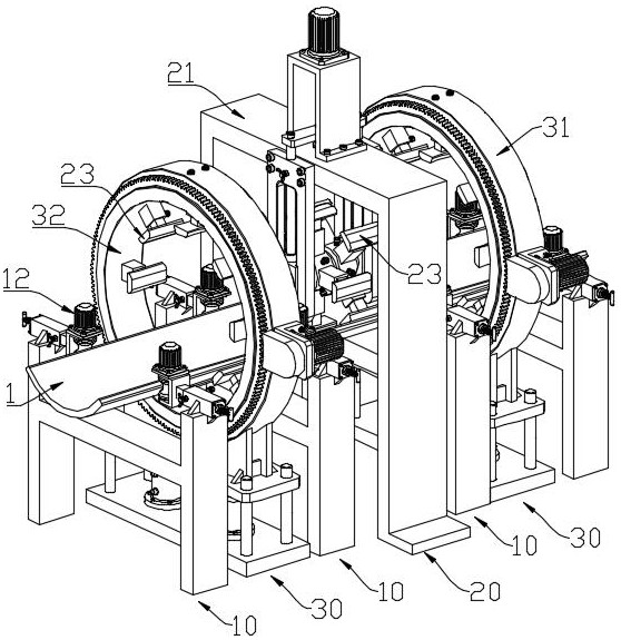
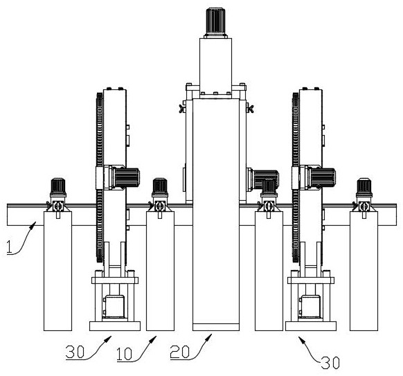
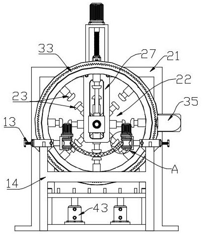
A polishing device for arc-shaped crack array antenna mounting plate, the conveying mechanism includes a pair of parallel conveying wheels for conveying the antenna mounting plate, the distance between the conveying wheels is adjustable, and the conveying wheels are connected with driving motors, the conveying mechanism There are multiple groups; there is at least one set of inner arc surface polishing mechanism. The inner arc surface polishing mechanism includes a gantry frame and a rotating part. The rotating part is evenly equipped with multiple polishing brushes along the circumference. The distance is adjustable; there is at least one set of outer arc surface polishing mechanism, which is located between the conveying mechanisms, at least one set of conveying mechanisms is provided between the inner arc surface polishing mechanism and the outer arc surface polishing mechanism, and the outer arc surface polishing mechanism includes the outer ring The seat and the inner ring coaxially rotated in the outer ring seat, the bottom of the outer ring seat is equipped with a lifting mechanism, and the inner wall of the inner ring is evenly equipped with a plurality of polishing brushes along the circumference, and the position of the polishing brushes along the normal direction of the inner ring can be adjusted . It can polish mounting plates with different thicknesses and different structures, and the polishing efficiency is high.

Description

technical field [0001] The invention belongs to the field of slot positive antenna manufacturing and processing, and in particular relates to a polishing device for an arc-shaped slot array antenna mounting plate. Background technique [0002] The slotted array antenna is usually a planar array structure. With the gradual expansion of antenna coverage, more and more slotted array antennas are required to be installed on a curved surface, which requires that the antenna mounting plate used to install the slotted antenna be processed into a design The arc-shaped structure of the antenna is used to obtain the arc-shaped slot array antenna. In order to improve the accuracy of the slot array antenna, there are also high requirements for the machining accuracy of the inner and outer arc surfaces of the antenna mounting plate. At present, most antenna mounting plates are cast or Formed by bending the board. The precision of the inner and outer curved surfaces of the antenna mounti...

Claims


Application Information

Patent Timeline
Patent Type & Authority Patents(China)
IPC IPC(8): B24B29/02B24B41/00B24B41/06
CPCB24B29/02B24B41/005B24B41/06
Inventor 李平
Owner CHENGDU NANJIAO TECH
Why Eureka
Try Eureka