
Hazardous gas leakage detection inspection robot and inspection method

An inspection robot and leak detection technology, applied in the field of inspection robots, can solve the problems of high degree and concentration of gas leakage, weak environmental adaptability of control methods, difficult maintenance, etc., and achieves low computing power and power consumption requirements. The effect of normal operation ability and labor cost reduction

Active Publication Date: 2021-03-09
BEIJING INSTITUTE OF TECHNOLOGYGY
View PDF9 Cites 6 Cited by
  • Summary
  • Abstract
  • Description
  • Claims
  • Application Information

AI Technical Summary

Problems solved by technology

[0004] Existing dangerous gas detection devices are often fixed in one position, and this device has the following defects: when the gas detection device detects a dangerous gas leak, often the gas has leaked a large amount of gas from the leak source, and the gas leaks to the position of the detection device And when it is sensed, the degree and concentration of gas leakage on site are already very high, which seriously threatens the safety of personnel on site
The existing research on robots with dangerous gas detection functions is still in its infancy, and there are mainly technical problems such as weak environmental adaptability of its control methods, low efficiency, single technologies such as environmental detection sensors, and incomplete functions.
[0006] The fixed-point detection of hazardous gas detection devices has the following defects: when the gas detection device detects a dangerous gas leak, often the gas has leaked a large amount of gas from the source of the leak, and when the gas leaks to the position of the detection device and is sensed, the on-site gas leak The degree and concentration are already very high, which seriously threatens the safety of personnel on site
Therefore, this device has problems such as poor timeliness and low detection accuracy when performing gas detection.
Although increasing the arrangement density of devices can solve the problem of poor timeliness to a certain extent, the number of equipment installed is huge, it is not easy to maintain, and the cost of equipment and installation costs increase exponentially
[0007] The existing research on mobile robots with dangerous gas detection function is less, and the popularity rate of traditional dangerous gas detection robots is not high. The staff can only detect the occurrence of dangerous gas leakage on site, but cannot lock the source of the leakage. Therefore, the performance of ordinary sensors greatly limits the detection performance of gas detection robots
2. The autonomous inspection method is not suitable for the general environment. Generally speaking, the autonomous inspection method of the inspection robot is closely related to the performance of the controller. Nowadays, the relevant research direction is mainly developed towards the direction of strong reliability and small amount of calculation.

Method used


Image

  • Hazardous gas leakage detection inspection robot and inspection method
  • Hazardous gas leakage detection inspection robot and inspection method
  • Hazardous gas leakage detection inspection robot and inspection method

Examples


Embodiment 1

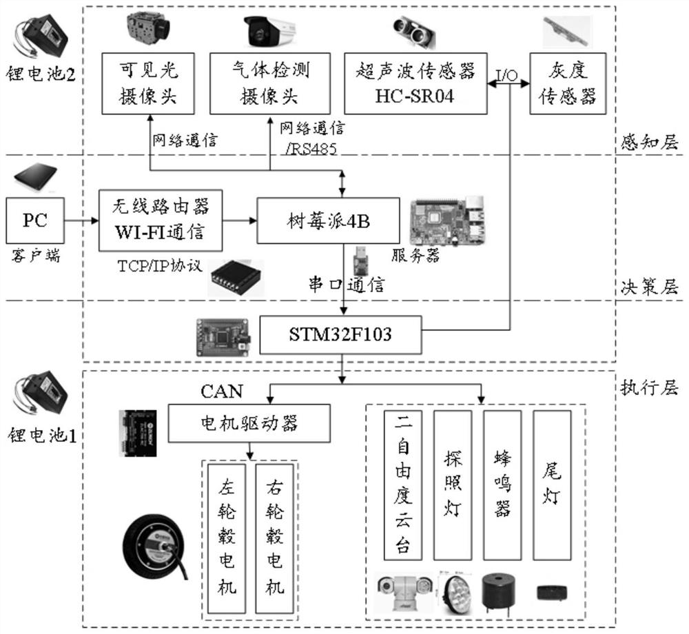
[0059] Embodiment 1: Embodiment 1 of the present invention provides a hazardous gas detection inspection robot system, which mainly includes a robot mechanical system, a sensor system, a control system, an electrical system and a communication system.

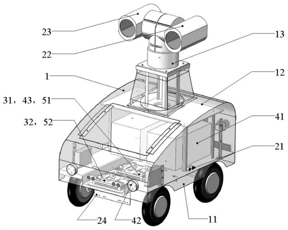
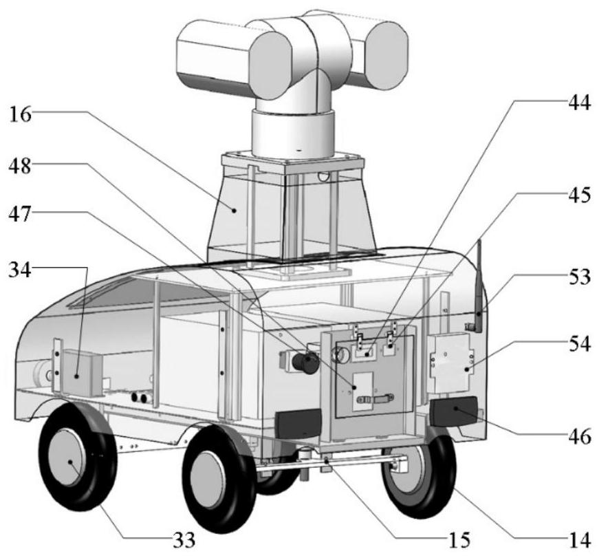
[0060] The mechanical system includes a chassis structure 11 , a casing 12 , a platform 13 , a driven wheel 14 , a driven wheel bogie 15 , and a platform support frame 16 . The chassis 11 is the support of each component of the robot, and carries each component of the system. The robot shell 12 is installed on the top of the chassis 11, fixed by a support frame, and the system hardware is sealed and protected (waterproof and dustproof). The gimbal 13 is a two-degree-of-freedom gimbal. The upper part is equipped with two housings that are respectively equipped with a high-definition visible light camera 22 and an optical gas infrared thermal imaging camera. Direction rotation range -90°~+90° pose adjustment to achieve real-time...

Embodiment 2

[0069] Embodiment 2: Embodiment 2 of the present invention provides a robot inspection method suitable for indoor semi-structured environments. This method can abandon manual intervention, realize automatic and autonomous patrol movement under a fixed trajectory, and can effectively avoid collisions with dynamic obstacles in the environment. This method has the advantages of simple control method, low calculation amount and low cost.

[0070] The inspection method adopted in the present invention takes into account the activity mode between human activities. In many cases, when we avoid behaviors during exercise, we often judge whether we should reduce our walking by judging the movement trend and speed of dynamic objects. speed, and we tend not to change the original walking path unless in a crisis state of collision. According to this general situation, the present invention plans a patrol route suitable for the current indoor environment in advance when considering the des...


PUM


Abstract

The invention provides a hazardous gas leakage detection inspection robot and an inspection method. Through a carried high-performance optical gas thermal imager, various common hazardous gases can bepresented in a monitoring video in a visual mode, the sensitivity is high, a tiny gas leakage phenomenon can be detected, and thus a gas leakage position can be accurately positioned. According to the hazardous gas detection method, on the basis of a fixed track inspection method, various possible dynamic obstacle motion behaviors are considered, a set of motion algorithm suitable for wide conditions is formulated, the algorithm is simple in arithmetic logic and low in calculation amount, the requirements for the calculation capacity and power consumption of a controller are low, and the hardware cost can be effectively saved. On the inspection function, the robot moves stably, dynamic obstacles typical for human beings can be effectively avoided, and the normal operation capacity in a man-machine coexistence environment is effectively achieved.

Description

technical field [0001] The invention belongs to the technical field of inspection robots, and in particular relates to a dangerous gas leakage detection inspection robot and an inspection method. Background technique [0002] Hazardous gas leakage can cause a series of hazards to human safety and equipment reliability, especially in the natural gas industry, chemical plants, biogas digesters, etc. Dangerous gases mainly include toxic and harmful gases (such as sulfur dioxide, carbon monoxide, etc.) and flammable and explosive gases (such as methane, etc.). These gases are often colorless and odorless, and their leakage is difficult to be detected by the staff. Therefore, the detection of dangerous gases has become one of the important problems to be solved urgently in the field of safety emergency and industrial production. [0003] For hazardous gas leakage sites, timely and correct judgment largely depends on accurate accident site data, which requires emergency personnel...

Claims


Application Information

Patent Timeline
Patent Type & Authority Applications(China)
IPC IPC(8): B25J9/16B25J13/08B25J19/02
CPCB25J9/1697B25J9/1602B25J9/1679B25J13/087B25J19/023
Inventor 高学山李敬业付小龙兰冰青高锐梁鹏
Owner BEIJING INSTITUTE OF TECHNOLOGYGY
Learn More