
Collaborative robot joint with single encoder

A robot joint and single-coding technology, applied in the field of robotics, can solve problems such as the inability to realize the zero return function of absolute position memory, the inability to realize the high-precision force sensing function, and the high requirement for the diameter of the joint center cable tube, so as to shorten the force transmission route, reduce joint structure complexity, reduce the effect of requirements

Pending Publication Date: 2021-03-09
716TH RES INST OF CHINA SHIPBUILDING INDAL CORP +1
View PDF2 Cites 7 Cited by
  • Summary
  • Abstract
  • Description
  • Claims
  • Application Information

AI Technical Summary

Problems solved by technology

However, this dual-encoder structure makes the joint structure complex, requires a high diameter of the joint center cable tube, and has low force sensing accuracy, making it difficult to achieve high-precision compliant control
In order to solve the problem, the patent CN210061184U uses a multi-turn absolute value encoder to realize the motion control of the robot joint, but this method cannot realize the high-precision force sensing function
Patents such as CN109895122A use absolute encoders and torque sensors to realize the motion control and force perception of the driving device, but this device cannot realize the absolute position memory (power-off protection) and zero return function, and at the same time, the lack of brakes causes the joints to be unable to perform emergency braking. Move and maintain, there are certain safety hazards
Patents such as CN108015799A use encoders and torque sensors to realize motion control and force perception of the driving device, but this device cannot realize absolute position memory (power-off protection) and zero return functions, and at the same time, due to the staggered setting of the axes of the motor and the reducer, resulting in structural Complicated and difficult for hollow wiring

Method used


Image

  • Collaborative robot joint with single encoder
  • Collaborative robot joint with single encoder
  • Collaborative robot joint with single encoder

Examples


Embodiment Construction

[0024] In order to make the purpose, technical solution and advantages of the present application clearer, the present application will be further described in detail below in conjunction with the accompanying drawings and embodiments. It should be understood that the specific embodiments described here are only used to explain the present application, and are not intended to limit the present application.

[0025] It should be noted that if there is a directional indication (such as up, down, left, right, front, back...) in the embodiment of the present invention, the directional indication is only used to explain the position in a certain posture (as shown in the accompanying drawing). If the specific posture changes, the directional indication will also change accordingly.

[0026] In addition, if there are descriptions involving "first", "second" and so on in the embodiments of the present invention, the descriptions of "first", "second" and so on are only for descriptive ...


PUM


Abstract

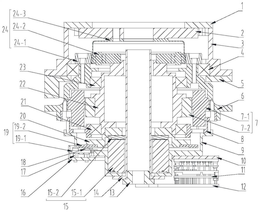
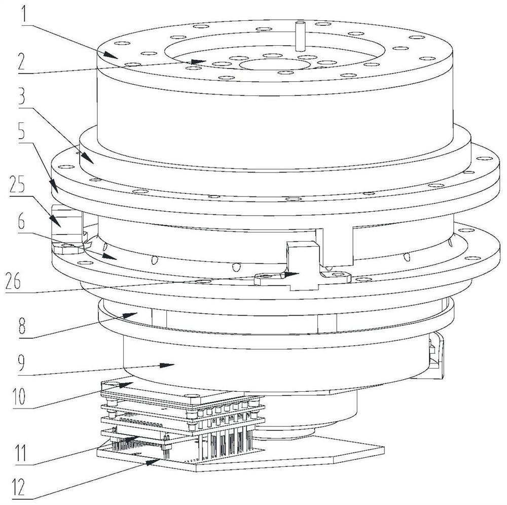
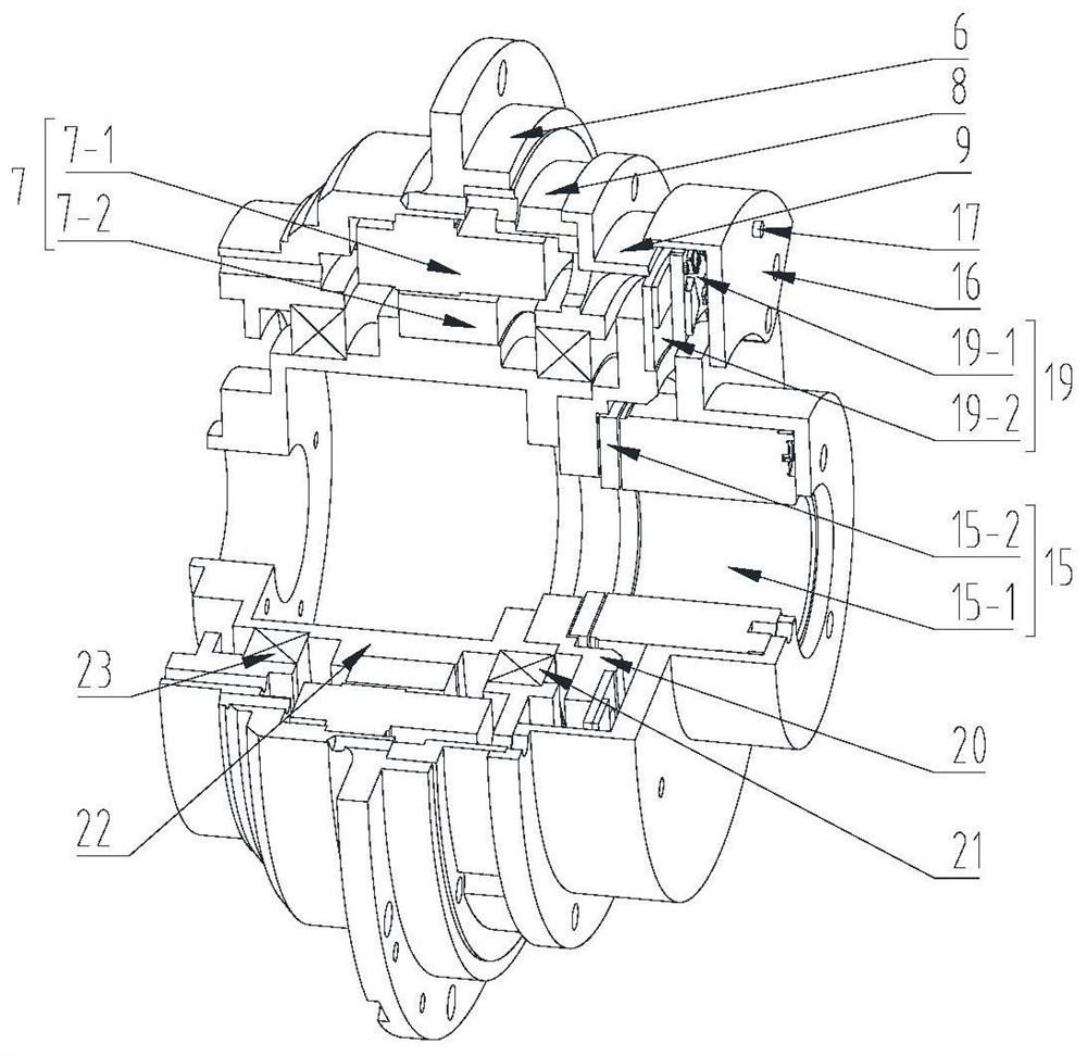
The invention discloses a collaborative robot joint with a single encoder, and belongs to the technical field of robots. The joint comprises an output flange, a torque sensor, a harmonic reducer, a frameless direct-drive torque motor, an input flange, a multi-turn absolute value encoder and a brake, wherein an output flange and the input flange can rotate relatively; the output end of the frameless direct-drive torque motor is connected with the torque sensor and the output flange through the harmonic reducer; and the input end of the frameless direct-drive torque motor is connected with the brake and the absolute value encoder. The collaborative robot joint provided by the invention has the functions of force sensing, absolute position memory, zero returning and the like, a collaborativerobot composed of the joint can work cooperatively with people in a semi-structure environment, and the the collaborative robot joint has the advantages of being high in precision force sensing function, compact in structure, high in rigidity, good in expandability and the like.

Description

technical field [0001] The invention belongs to the technical field of robots, in particular to a collaborative robot joint with a single encoder. Background technique [0002] Collaborative robots can combine their own high precision and high tolerance with the flexible adaptability of humans. They have the characteristics of human-machine integration, safety and ease of use, sensitivity, precision, and flexibility. They are not only suitable for small and medium batches, multi-variety, and user customization in the industrial field. It also has potential application prospects in the fields of social services and rehabilitation medicine in response to aging. In recent years, the research and development of modular integrated joints, which are an important part of collaborative robots, has attracted increasing attention. Robotic joints with light weight and high energy density can realize the lightweight, large load-to-weight ratio, flexibility, ease of use, and safety of co...

Claims


Application Information

Patent Timeline
IPC IPC(8): B25J17/02
CPCB25J17/02
Inventor 胡明伟孙宏伟邹金欣李萌萌赵昀何家健王晶晶杨迎霞
Owner 716TH RES INST OF CHINA SHIPBUILDING INDAL CORP
Learn More