Pressure-adjustable grouting system and grouting method based on special grouting moving cavity

A technology of grouting system and grouting pressure, which is applied in soil protection, infrastructure engineering, construction, etc., can solve problems such as delaying construction period, increasing project construction cost, and increasing the number of grouting pipes, so as to avoid additional drilling , Improving the efficiency of on-site construction and saving the cost of engineering construction

Active Publication Date: 2021-03-09
ECONOMIC RES INST OF STATE GRID GANSU ELECTRIC POWER +1
View PDF6 Cites 3 Cited by
  • Summary
  • Abstract
  • Description
  • Claims
  • Application Information

AI Technical Summary

Problems solved by technology

[0004] The existing grouting pipe and the grouting valve pipe can only control the grouting pressure alone, which cannot meet the control of different grouting pressures for different depths and different geological soil layers. Most of the existi

Method used


Image

  • Pressure-adjustable grouting system and grouting method based on special grouting moving cavity
  • Pressure-adjustable grouting system and grouting method based on special grouting moving cavity

Examples


Embodiment 1

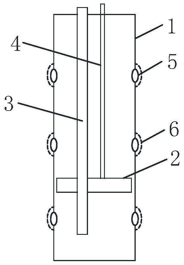
[0039]When it is necessary to apply different pressures to a single grouting valve tube, the movable piston and the grouting valve tube body generate closed cavities of different depths to realize multi-layer grouting in a single grouting valve tube, each layer can be According to the geological conditions, different grouting pressures are designed for the grouting depth, so that the present invention can carry out special grouting on the target soil layer, realize multi-layer grouting with a single pipe, and improve the efficiency of on-site construction.

[0040] The specific grouting method is:

[0041] The first step is to design the position of the spraying valve port according to the geological conditions;

[0042] The second step is to set out the line on site, determine the position of the grouting valve pipe and drill the well through the drilling machine;

[0043] The third step is to install the grouting valve pipe body, and place the movable piston, grouting pipe,...

Embodiment 2

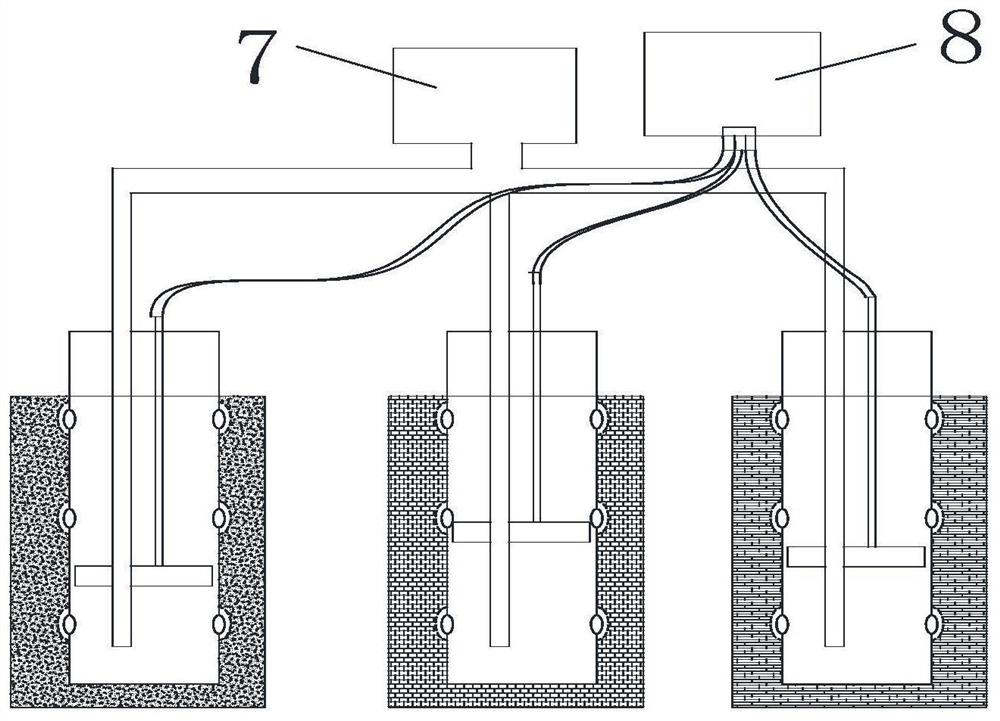
[0050] like figure 2 As shown, when the grouting system is used in different formations such as sand layers and soil layers, different pressures need to be applied to different grouting valve pipes. At this time, the movable piston and each grouting valve pipe body generate Grouting is performed on each grouting valve pipe by means of closed cavities of different depths.

[0051] The specific grouting method is:

[0052] The first step is to design the position of the spraying valve port according to the geological conditions;

[0053] The second step is to set out the line on site, determine the position of the grouting valve pipe and drill the well through the drilling machine;

[0054] The third step is to install the grouting valve pipe body, and place the movable piston, grouting pipe, and gas injection pipe in the grouting valve pipe body according to the design of the present invention

[0055] The fourth step is to confirm the grouting position of each grouting val...


PUM


Abstract

The invention discloses a pressure-adjustable grouting system and grouting method based on a special grouting moving cavity, and relates to the technical field of grouting. The grouting system comprises a main grouting pipe and a plurality of grouting valve pipes connected to the main grouting pipe, wherein each grouting valve pipe is located in an annular space in the wall of a drill hole, each grouting valve pipe comprises a grouting valve pipe body, and a guniting valve port is formed in each grouting valve pipe body; and a grouting pipe, an air injection pipe and a movable piston are arranged in each grouting valve pipe body, the air injection pipes are connected with the movable pistons, air pressure is applied into the movable pistons through the air injection pipes, the movable pistons generate volume expansion after the air pressure is applied, therefore closed cavities are formed between the lower portions of the movable pistons and the grouting valve pipe bodies, and groutingis conducted in the grouting valve pipe bodies according to the positions of the movable pistons. According to the grouting system, pressure adjustment can be conducted on a single grouting valve pipe, so that special grouting is conducted on different target layers, and the on-site construction efficiency can be improved.

Description

technical field [0001] The invention relates to the technical field of grouting, in particular to a grouting system and a grouting method based on an adjustable pressure of a special grouting moving chamber. Background technique [0002] In foundation treatment engineering, pressure grouting has become a more conventional method, and pressure control in the process of grouting has become a difficult point in the project. Because the pressure control value is closely related to the geological conditions and the buried depth of the grouting port, this poses an extremely severe challenge to the pressure control of the single-pipe grouting. With conventional grouting pipes, the grouting pressure in a single pipe is consistent, and it is difficult to achieve different pressures at different depths, or different pressures in different geological soil layers. [0003] In the grouting foundation treatment process, the treatment effect and project construction cost largely depend on...

Claims


Application Information

Patent Timeline
IPC IPC(8): E02D15/02E02D3/12
CPCE02D15/02E02D3/12E02D2250/003E02D5/34
Inventor 王仕俊范雪峰付兵彬安宁姜明军张喆
Owner ECONOMIC RES INST OF STATE GRID GANSU ELECTRIC POWER
Why Eureka
Try Eureka