
Hydrostatic linear driving system

A linear drive and hydrostatic technology, applied in the direction of fluid pressure actuators, presses, accumulator devices, etc., can solve the problems of inability to achieve moving speed, etc., and achieve the effect of simple structure and compact structure

Pending Publication Date: 2021-03-09
KRUPP KAUTEX MASCHINENBAU GMBH
View PDF5 Cites 0 Cited by
  • Summary
  • Abstract
  • Description
  • Claims
  • Application Information

AI Technical Summary

Problems solved by technology

[0004] The compensating container implemented as a differential cylinder has the result that the movement of the master cylinder in rapid travel always takes place against the resistance of the second cylinder as compensating container, thus making it impossible to achieve a high speed in rapid travel. moving speed while having a large force in the dynamic range

Method used


Image

  • Hydrostatic linear driving system
  • Hydrostatic linear driving system
  • Hydrostatic linear driving system

Examples


Embodiment Construction

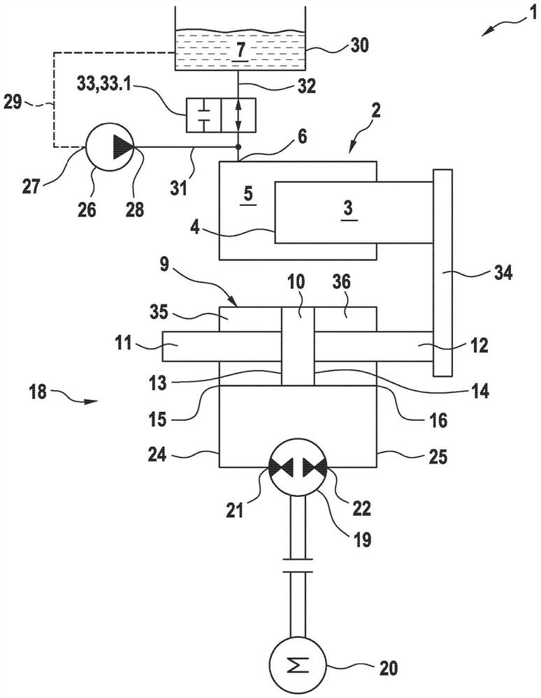
[0049] figure 1 A first embodiment of a hydrostatic linear drive system 1 with a single-acting cylinder 2 embodied as a plunger cylinder is shown. The plunger cylinder comprises a piston rod 3 , a first hydraulically effective surface 4 and a first cylinder chamber 5 with a first fluid connection 6 for hydraulic fluid 7 . Since the single-acting cylinder 2 is embodied as a plunger cylinder, the piston rod 3 is simultaneously a piston. The end side of the piston rod 3 facing the cylinder chamber 5 is a piston face and is hydraulically active.

[0050] The first hydraulically effective surface 4 of the single-acting cylinder 2 can be acted upon with hydraulic fluid 7 in the extension direction 8 via the first fluid connection 6 .

[0051] The linear drive system 1 also has a synchronous cylinder 9 with piston rods 11 , 12 on both sides of the piston 10 . The annular piston surfaces surrounding the piston rods 11 , 12 form a second hydraulically effective surface 13 and a thir...


PUM


Abstract

The invention relates to a hydrostatic linear drive system, in particular for a closure unit of a blow mold installation. The linear drive system has a simpler and more compact structure while havinga higher retraction and expansion speed in quick motion, stronger force in power motion, and reduced energy consumption. In order to provide the linear drive system, a cylinder device is proposed, extension movement in quick motion is brought by separate hydraulically active faces which are independent of a larger hydraulically active face which a pressurized hydraulic fluid act on only in power motion. During the extension movement in the power motion, the hydraulically active faces interact to contribute to generation of high force with a compact structure of the drive system.

Description

technical field [0001] The invention relates to a hydrostatic linear drive system, in particular for a closure unit of a blow molding plant. Background technique [0002] Hydrostatic linear drive systems are also used, for example, in hydraulic presses, deep drawing machines or injection molding machines. Such machines usually have several motion sequences. One of these motion sequences is the so-called power stroke, in which high forces act at low speeds on the workpiece to be machined or the component to be moved. The other of these movement sequences is the so-called rapid path (Eilgang), with which less force is exerted, but a faster movement can be achieved. [0003] Such a linear drive system is known, for example, from DE 10 2016 113 882 A1. Known linear drive systems have a hydraulic pump driven by an electric motor and capable of redirecting the flow direction. The hydraulic pump is used to provide a variable volumetric flow of hydraulic fluid in a closed hydrau...

Claims


Application Information

Patent Timeline
Patent Type & Authority Applications(China)
IPC IPC(8): F15B11/04F15B11/17F15B11/22F15B1/02F15B13/06B30B15/16B29C49/56
CPCF15B11/04F15B11/17F15B11/22F15B1/024F15B13/06B30B15/161B29C49/56F15B2211/20576F15B2211/212F15B2211/782F15B11/036F15B11/022F15B2211/20561F15B2211/27F15B2211/20546F15B2211/7055F15B2211/775F15B1/26F15B1/021F15B15/149F15B15/18
Inventor 阿恩特·韦伦贝格明卡·切科尔斯基奥尔洛夫
Owner KRUPP KAUTEX MASCHINENBAU GMBH
Learn More