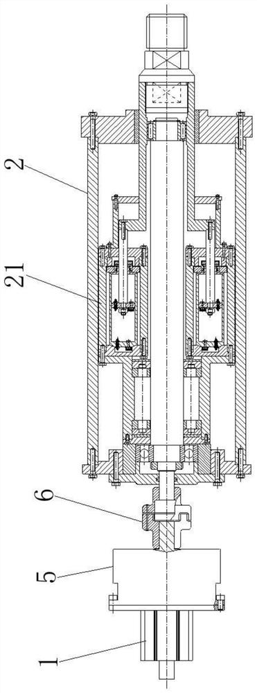
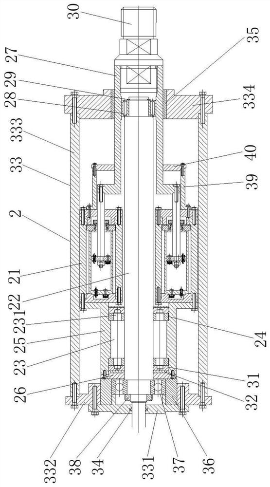
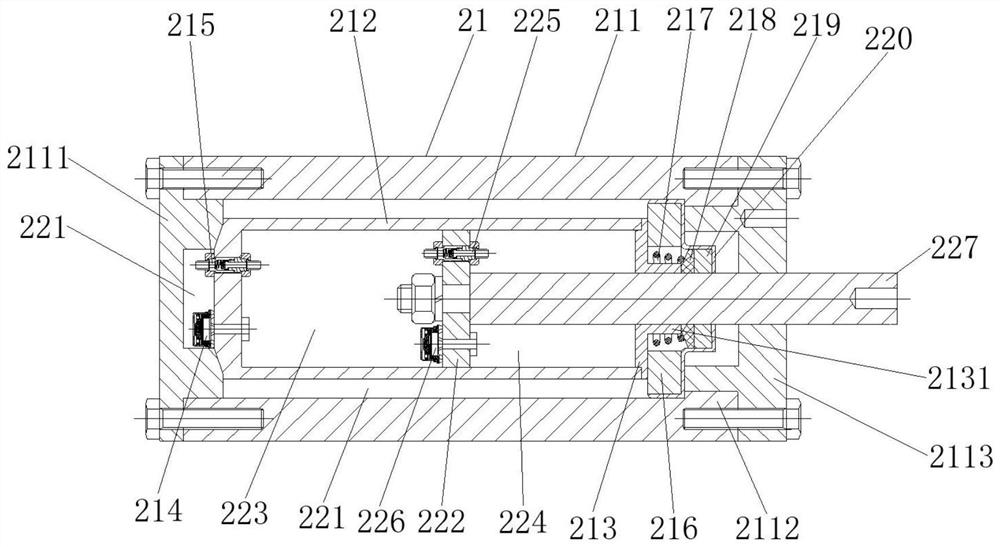
Electric loader with hydraulic buffer

A hydraulic buffer and loader technology, which is applied in the direction of transmission, electric components, electromechanical devices, etc., can solve problems such as difficult to guarantee load deviation, high loading accuracy requirements, and aging of the mechanical structure of the device, so as to ensure the coordination of stability and movement The effects of stability, continuous stability of load output, and improvement of load control range

Active Publication Date: 2022-05-06
TIANJIN UNIVERSITY OF TECHNOLOGY
View PDF11 Cites 0 Cited by
  • Summary
  • Abstract
  • Description
  • Claims
  • Application Information

AI Technical Summary

Problems solved by technology

Chinese patent CN201711488253.8 discloses a double-spring buffer device loaded by an electric cylinder. In the technical solution, due to the high rigidity of the double-spring buffer device, it is easily deformed and damaged after being subjected to an impact load, and the structure is relatively complicated, and the spring is It is prone to fatigue failure under repeated alternating stress, which will cause accelerated aging of the mechanical structure of the device, which is not conducive to later maintenance
Chinese patent CN201510137801.7 discloses a two-way double-action integrated loader. In the technical solution, two sets of butterfly springs are used as the load output and buffer components. Since the butterfly springs belong to special-shaped springs, the manufacturing accuracy The requirements are high, the processing cost is high, and the load deviation is difficult to guarantee
Chinese patent CN201610116836.7 discloses an axial loading device for the vibration detection table of a harmonic reducer. In this technical solution, a compression spring is used as a buffer component to output a flexible load. Since the spring is in a compressed state, the axial loading device only Capable of outputting compressive loads, unable to provide dynamic or static loads in the tensile direction
When the electric loader is proposed to be able to output dynamic loads or static loads in both directions of tension and compression, and requires high loading accuracy, good load stability, fast loading feedback response, and compact mechanical structure, etc., the existing electric loader The device does not meet the requirements

Method used


Image

  • Electric loader with hydraulic buffer
  • Electric loader with hydraulic buffer
  • Electric loader with hydraulic buffer

Examples


Embodiment Construction

[0027] It should be noted that, in the case of no conflict, the embodiments of the present invention and the features in the embodiments can be combined with each other.

[0028] In describing the present invention, it should be understood that the terms "center", "longitudinal", "transverse", "upper", "lower", "front", "rear", "left", "right", " The orientations or positional relationships indicated by "vertical", "horizontal", "top", "bottom", "inner" and "outer" are based on the orientations or positional relationships shown in the drawings, and are only for the convenience of describing the present invention and Simplified descriptions, rather than indicating or implying that the device or element referred to must have a particular orientation, be constructed and operate in a particular orientation, and thus should not be construed as limiting the invention. In addition, the terms "first", "second", etc. are used for descriptive purposes only, and should not be understood ...


PUM


Abstract

The invention provides an electric loader with a hydraulic buffer device, belonging to the field of mechanical electric servo loading, comprising a motor and a loading mechanism, the output end of the motor is connected to the input end of the loading mechanism, the loading mechanism includes a buffer assembly, and the buffer assembly includes a first A casing, a working cylinder, a guide seat, a compensation valve, a compression valve, a sealing ring, a spring, an oil seal, a gasket, an oil seal cover, a moving piston, a circulation valve, an extension valve and a piston rod. The first casing includes a first left end cover, a storage The oil cylinder barrel and the right end cap, the first left end cap, the oil storage cylinder barrel and the right end cap are arranged coaxially from left to right. The buffer assembly of the invention can effectively relieve the rigid impact of the external load, play the function of buffering and damping, and protect the loading device and the loaded components.

Description

technical field [0001] The invention belongs to the field of mechanical and electric servo loading, and relates to an electric loader with a hydraulic buffer device. Background technique [0002] With the development of servo control technology, electrical and electronic products and precision transmission components, electric loading devices have been widely used in aerospace, intelligent manufacturing, medical equipment, engineering machinery, and national defense and military industries. Compared with traditional mechanical and hydraulic loading devices , The electric loading device has many advantages such as high transmission efficiency, good electrical synchronization, stable operation, compact structure, convenient maintenance, etc., and is more and more favored by the majority of scientific and technological workers. [0003] In the prior art, mechanical springs are often used as load buffering components of electric loading devices. Chinese patent CN201711488253.8 ...

Claims


Application Information

Patent Timeline
Patent Type & Authority Patents(China)
IPC IPC(8): F16F15/023F16F9/34F16H25/22F16H25/24H02K7/06H02K7/10
CPCF16F15/023F16F9/34F16H25/2247F16H25/2418H02K7/06H02K7/10F16H2025/2075
Inventor 闫世程薛亚红葛家尚张健钊王占朝
Owner TIANJIN UNIVERSITY OF TECHNOLOGY
Why Eureka
Try Eureka