
Multi-dimensional parallel swing wave power generation device

A technology of wave power generation and parallel connection, which is applied in the direction of ocean energy power generation, engine components, machines/engines, etc., can solve the problems of low utilization rate of wave energy, etc., and achieve the effect of compact structure, high space utilization rate and improved service life

Inactive Publication Date: 2016-12-07
SHANGHAI JIAO TONG UNIV
View PDF6 Cites 0 Cited by
  • Summary
  • Abstract
  • Description
  • Claims
  • Application Information

AI Technical Summary

Problems solved by technology

Through the combined effect of the floating body and the balance floating body, the device transfers the energy of the floating body when it descends in the vertical direction to the flywheel of the output shaft through the pulley, and then ensures the normal power generation of the permanent magnet synchronous generator on the output shaft through the inertia of the flywheel. The device has the following disadvantages: the device only utilizes the energy when the floating body descends, and does not utilize the energy of the floating body rising and the lateral swing of the waves, resulting in a low utilization rate of wave energy

Method used


Image

  • Multi-dimensional parallel swing wave power generation device
  • Multi-dimensional parallel swing wave power generation device
  • Multi-dimensional parallel swing wave power generation device

Examples


Embodiment Construction

[0053] The present invention will be described in detail below in conjunction with specific embodiments. The following examples will help those skilled in the art to further understand the present invention, but do not limit the present invention in any form. It should be noted that those skilled in the art can make several modifications and improvements without departing from the concept of the present invention. These all belong to the protection scope of the present invention.

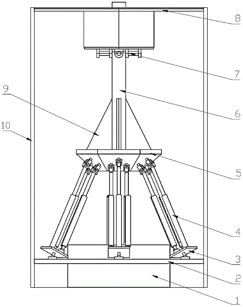
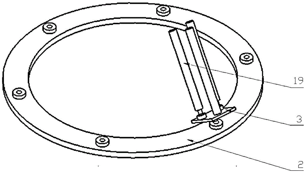
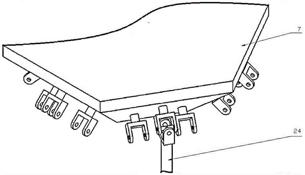
[0054] Such as figure 1As shown, in this embodiment, the present invention provides a multi-dimensional parallel swing wave power generation device, including a mixed oil tank 1, a lower platform 2, a rotating platform 3, six groups of parallel hydraulic cylinders 4, an upper platform 5, a swing rod 6, Three-degree-of-freedom motion pair 7, top cover 8, rib 9, buoyancy tank 10. The top cover 8 is fixedly connected to the inner wall of the upper end of the buoyancy tank 10; the outer ring of the t...


PUM


Abstract

The invention provides a novel multi-dimensional parallel connecting swing wave power generation device which comprises a mixed oil tank, a lower platform, rotary platforms, six sets of parallel hydraulic cylinders, an upper platform, a swing rod, a three-freedom-degree kinematic pair, a top cover, a rib plate and a floating box. The top cover is fixedly connected to the inner wall of the upper end of the floating box. The outer ring of the three-freedom-degree kinematic pair is fixed with the top cover, and the inner ring of the three-freedom-degree kinematic pair and the swing rod form a moving pair. One end of the swing rod penetrates through the top wall of the floating box and is fixedly connected to an external device, and the other end of the swing rod is fixedly arranged on the upper platform. Piston rods of the six sets of parallel hydraulic cylinders and the upper platform are in universal joint connection, and cylinder bodies of the six sets of parallel hydraulic cylinders and the rotary platforms form two spherical pairs. The rotary platforms and the lower platform form spherical pairs. The lower platform is fixedly arranged on the mixed oil tank, and the mixed oil tank is fixedly connected with the bottom of the floating box. The novel multi-dimensional parallel connecting swing wave power generation device has the advantages of being high in power generation capacity, high in sea wave energy utilization rate, long in service life, small in pollution and the like, and is capable of absorbing sea wave swing energy in the horizontal direction, and capable of absorbing sea wave energy in the vertical direction.

Description

technical field [0001] The invention relates to the technical field of wave power generation, in particular to a multi-dimensional parallel swing wave power generation device. Background technique [0002] The undulating sea is a kind of marine resource. On the sea surface of 1 square kilometer, there is 200,000 kilowatts of wave motion energy per second. There are various forms of wave power generation, some use the up and down fluctuations of waves, some use the lateral movement of waves, and some use the pressure changes in water generated by waves, etc. [0003] In 1964, Japan was the first to manufacture a beacon light that uses ocean waves to generate electricity. Subsequently, many countries in the world, such as the United Kingdom, the United States, Canada, Finland, Denmark, France, etc., are researching and testing wave power generation, and have successively proposed hundreds of power generation device designs. However, due to various technical problems, the re...

Claims


Application Information

Patent Timeline
Patent Type & Authority Patents(China)
IPC IPC(8): F03B13/14
CPCY02E10/30
Inventor 马春翔钱超陈康陈伟聪郑茂琦高峰
Owner SHANGHAI JIAO TONG UNIV
Learn More