Measuring device for wet-end dragging force of dragging system

A measuring device and drag force technology, which is applied in the field of drag force measurement devices, can solve the problems of higher cost than a test on a lake, measurement of drag force at the wet end of a difficult tow system, and high related costs

Active Publication Date: 2021-03-09
中国船舶重工集团有限公司第七一0研究所
View PDF8 Cites 0 Cited by
  • Summary
  • Abstract
  • Description
  • Claims
  • Application Information

AI Technical Summary

Problems solved by technology

[0002] Accurately measuring the drag force at the wet end of the towing system can facilitate the analysis of the towing performance of the towing body and the towing system, and effectively guide the optimal design of the towing body and the towing system. The wet end drag force (i.e. the fluid force of the drag body) is generally measured in the towing pool through the forced model test, but the number of the drag body states that can be measured by the pool test is limited, and the related costs of the pool test are getting higher and higher, and the related costs have been reduced. It is much higher than the cost of a test on a lake. Therefore, if the drag force at the wet end of the towing system can be accurately measured directly in the test on the lake, it will not only save the research and development steps of the tow body pool test, simplify the research and development process, but also save research and development costs. , but the current test on the lake can only measure the tension at the dry end of the towing system (that is, the overall drag force of the tow cable and the towing body), and it is difficult to effectively and accurately measure the drag force at the wet end of the towing system (that is, the fluid force of the towing body)

Method used


Image

  • Measuring device for wet-end dragging force of dragging system
  • Measuring device for wet-end dragging force of dragging system
  • Measuring device for wet-end dragging force of dragging system

Examples


Embodiment Construction

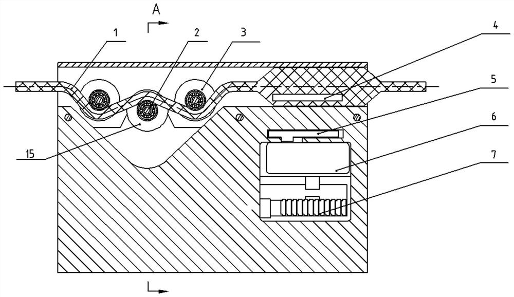
[0027] See attached figure 1 , 2 ,, a device for measuring drag force at the wet end of a towing system. The towing cable 1 in the towing system includes: a core wire for data transmission, a core wire for power supply, and a pair of twisted pairs. Twisted pair wires are used to communicate the measured wet end drag force data.

[0028] The first electromagnetic induction coil 4 is pre-embedded in the watertight layer at the wet end of the towing cable 1, and the first electromagnetic induction coil 4 and the towing cable 1 are vulcanized as one. After vulcanization, the diameter of this section of the towing cable 1 will become thicker. The electromagnetic induction coil 4 is connected in series with the twisted pair.

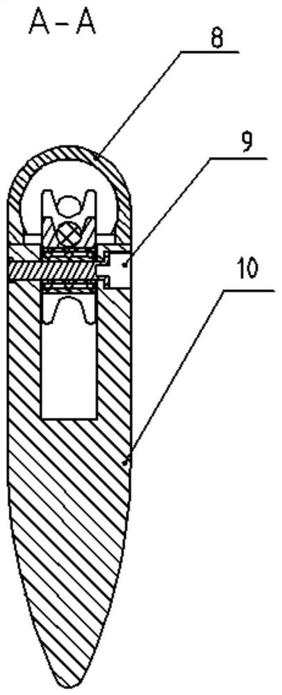
[0029] See attached Figure 3-8 , the tow cable 1 is arranged between the pad 8 and the guide vane 10; both the support pad 8 and the guide vane 10 have a guide shape to reduce the fluid force and the influence on the tension of the tow cable. The guide va...


PUM


Abstract

The invention relates to the technical field of underwater dragging detection, in particular to a dragging force measuring device. The invention discloses the measuring device for the wet-end draggingforce of a dragging system. According to the device, a dragging cable in the dragging system comprises a dragging body transmission data core wire, a power supply core wire and a pair of twisted pairs; a first electromagnetic induction coil is pre-buried in a watertight layer at the wet end of the dragging cable, and the electromagnetic induction coil is connected with the twisted pairs in series; the dragging cable is arranged between a supporting tile and a flow guide fin; the dragging cable is lapped on a force measuring roller, and two ends of the dragging cable are respectively pressed by limiting rollers; the force measuring roller is connected with a pin shaft type sensor through a fixed shaft pin; and a second electromagnetic induction coil and a wet-end data processing circuit board are arranged below the first electromagnetic induction coil. According to the invention, the wet-end tension of the dragging system in different states can be directly measured in actual environments such as lakes or seas under non-laboratory conditions, and measured data can be transmitted back in real time by using an electromagnetic coupling communication technology without passing througha dragging body.

Description

technical field [0001] The invention relates to the technical field of underwater drag detection, in particular to a drag force measuring device. Background technique [0002] Accurately measuring the drag force at the wet end of the towing system can facilitate the analysis of the drag performance of the towing body and the towing system, and effectively guide the optimal design of the towing body and the towing system. The forced model test in the pool is completed, but the number of towed body states that can be measured by the pool test is limited, and the related costs of the pool test are getting higher and higher, and the related cost is far higher than the cost of a lake test. Accurately measuring the drag force at the wet end of the towing system in the lake test can not only save the research and development steps of the towing pool test, simplify the research and development process, but also save research and development costs. However, the current lake test can ...

Claims


Application Information

Patent Timeline
Patent Type & Authority Applications(China)
IPC IPC(8): G01M10/00G01L5/10
CPCG01M10/00G01L5/10Y02A90/30
Inventor 贺平王盟陆伟
Owner 中国船舶重工集团有限公司第七一0研究所
Why Eureka
Try Eureka