Eureka AIR delivers breakthrough ideas for toughest innovation challenges, trusted by R&D personnel around the world.

Soft material fluidity detection device

A detection device and fluidity technology, applied in the directions of flow characteristics, measurement device, analysis materials, etc., can solve the problems of complex steps, large random errors, poor device stability, etc., and achieve good real-time detection, wide application range, and convenient experimentation. Effect

Active Publication Date: 2021-03-12
TECH & ENG CENT FOR SPACE UTILIZATION CHINESE ACAD OF SCI
View PDF13 Cites 2 Cited by
  • Summary
  • Abstract
  • Description
  • Claims
  • Application Information

AI Technical Summary

Problems solved by technology

[0006] Publication number: CN 104297103 A patent discloses 3D printing construction mortar workability test device and application, the program has the following defects: 1. The real-time pressure value during the process of material compression cannot be obtained
2. The accuracy is low; the extrusion time recorded by this scheme is obtained by manual timing when the push rod is lowered by 100mm. Although the data processing method of taking the average value is adopted in the follow-up, there are still large random errors in it
3. The stability of the device is poor
In this scheme, only the ring bracket is used to fix the injection cylinder, which will easily cause the injection cylinder to tilt when the load is placed on it, thus affecting the progress of the experiment and the collection of experimental data
[0007] The patent with the publication number CN 110243724 A discloses a 3D printing mortar extrusion performance quantitative detection device and method, which has the following defects: 1. The preliminary steps of the experiment preparation are complicated
2. In the experiment, only the force change was monitored in real time
3. The overall structure is a vertical structure. During the pressure implementation process, it will affect the motor and other components in the main structure.
[0008] According to the above problems, although some slurries have certain fluidity, they cannot be used on light-curing machines if they drip to a certain extent and solidify directly.
The fluidity, dispersion and viscosity parameters of soft matter materials need to be perfectly unified with the working parameters of the printer used, otherwise there will be collapse, deformation and other phenomena, resulting in printing failure

Method used


Image

  • Soft material fluidity detection device
  • Soft material fluidity detection device
  • Soft material fluidity detection device

Examples


Embodiment 1

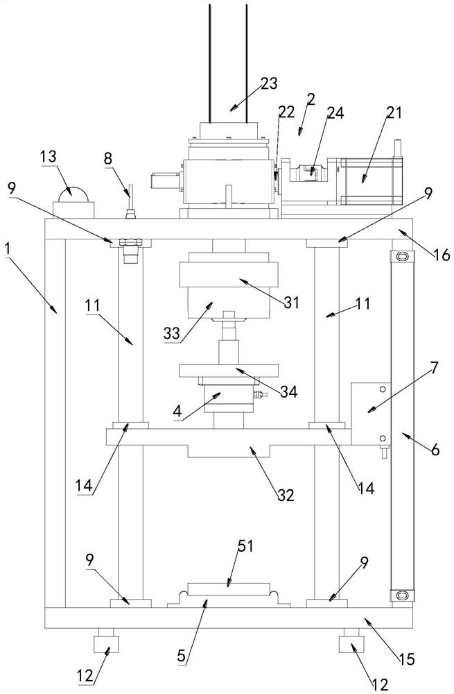
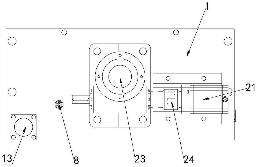
[0034] Such as figure 1 and figure 2 As shown, a soft material fluidity detection device of this embodiment includes a bracket 1, a driving device 2, an upper pressure mechanism 3, a pressure detection device 4, a lower support part 5 and a displacement detection device, and the driving device 2 is installed On the bracket 1, the driving device 2 is connected with the upper pressing mechanism 3 and drives the upper pressing mechanism 3 to move downward, and the lower supporting part 5 is located in the bracket 1 and on the upper Below the pressing mechanism 3 , the pressure detection device 4 is installed on the upper pressing mechanism 3 , and the displacement detecting device is installed on the support 1 and detects the displacement of the upper pressing mechanism 3 .

[0035]In this embodiment, the driving device is used to drive the upper pressing mechanism to move downward, and the upper pressing mechanism is used to squeeze the material on the lower support part. The ...

Embodiment 2

[0038] Such as figure 1 and figure 2 As shown, a soft material fluidity detection device of this embodiment includes a bracket 1, a driving device 2, an upper pressure mechanism 3, a pressure detection device 4, a lower support part 5 and a displacement detection device, and the driving device 2 is installed On the bracket 1, the driving device 2 is connected with the upper pressing mechanism 3 and drives the upper pressing mechanism 3 to move downward, and the lower supporting part 5 is located in the bracket 1 and on the upper Below the pressing mechanism 3 , the pressure detection device 4 is installed on the upper pressing mechanism 3 , and the displacement detecting device is installed on the support 1 and detects the displacement of the upper pressing mechanism 3 .

[0039] Such as figure 1 As shown, the upper pressing mechanism 3 of this embodiment includes a flange 31 and a pressure plate 32, the flange 31 is connected to the driving device 2, the pressure plate 32 ...

Embodiment 3

[0053] Such as figure 1 and figure 2 As shown, a soft material fluidity detection device of this embodiment includes a bracket 1, a driving device 2, an upper pressure mechanism 3, a pressure detection device 4, a lower support part 5 and a displacement detection device, and the driving device 2 is installed On the bracket 1, the driving device 2 is connected with the upper pressing mechanism 3 and drives the upper pressing mechanism 3 to move downward, and the lower supporting part 5 is located in the bracket 1 and on the upper Below the pressing mechanism 3 , the pressure detection device 4 is installed on the upper pressing mechanism 3 , and the displacement detecting device is installed on the support 1 and detects the displacement of the upper pressing mechanism 3 .

[0054] Such as figure 1 As shown, the upper pressing mechanism 3 of this embodiment includes a flange 31 and a pressure plate 32, the flange 31 is connected to the driving device 2, the pressure plate 32 ...


PUM


Abstract

The invention relates to a soft material fluidity detection device. The detection device comprises a support, a driving device, an upper pressing mechanism, a pressure detection device, a lower supporting part and a displacement detection device, the driving device is installed on the support, and the driving device is connected with the upper pressing mechanism and drives the upper pressing mechanism to move downwards; and the lower supporting part is located in the support and located below the upper pressing mechanism, the pressure detection device is installed on the upper pressing mechanism, and the displacement detection device is installed on the support and detects displacement of the upper pressing mechanism. The driving device is used for driving the upper pressing mechanism to move downwards, the upper pressing mechanism is used for extruding materials on the lower supporting part, the displacement detection device on the support and the pressure detection device on the upper pressing mechanism are used for obtaining a displacement measurement value and a force measurement value in the pressure implementation process at the same time, the flow characteristics of the material are obtained by measuring the relationship between the pressure and the displacement when the material is forced to move, the principle feasibility is high, and the result can be accurately compared.

Description

technical field [0001] The invention relates to the related technical field of fluidity detection of soft material materials, in particular to a fluidity detection device of soft material materials. Background technique [0002] 3D printing technology is a cutting-edge technology that combines material technology, digital modeling, information processing and other fields, breaking the thinking mode of subtractive manufacturing and becoming a new processing mode. At present, 3D printing technology is developing at a high speed and has received extensive attention at home and abroad. [0003] Ceramic materials are widely used in aerospace, industrial manufacturing, biomedicine and other fields due to their properties such as high compressive strength, high hardness, high temperature resistance, and poor electrical and thermal conductors. It is very difficult, costly and time-consuming to process ceramic materials using traditional techniques. However, 3D printing ceramic mat...

Claims


Application Information

Patent Timeline
IPC IPC(8): G01N11/00
CPCG01N11/00
Inventor 张可鑫刘兵山刘晓冬李鑫
Owner TECH & ENG CENT FOR SPACE UTILIZATION CHINESE ACAD OF SCI
Why Eureka
Eureka Blog
Learn More