Optical imaging lens and imaging equipment

A technology of optical imaging lens and imaging surface, which is applied in the field of imaging lens to achieve ultra-high resolution, convenient assembly, and satisfying requirements

Active Publication Date: 2022-04-12
JIANGXI LIANCHUANG ELECTRONICS CO LTD
View PDF5 Cites 0 Cited by
  • Summary
  • Abstract
  • Description
  • Claims
  • Application Information

AI Technical Summary

Problems solved by technology

However, most of the existing lenses on the market cannot meet the above requirements well. Therefore, it is urgent to develop an optical imaging lens with high resolution, large imaging area, and large aperture that can cooperate with ADAS.

Method used


Image

  • Optical imaging lens and imaging equipment
  • Optical imaging lens and imaging equipment
  • Optical imaging lens and imaging equipment

Examples


no. 1 example

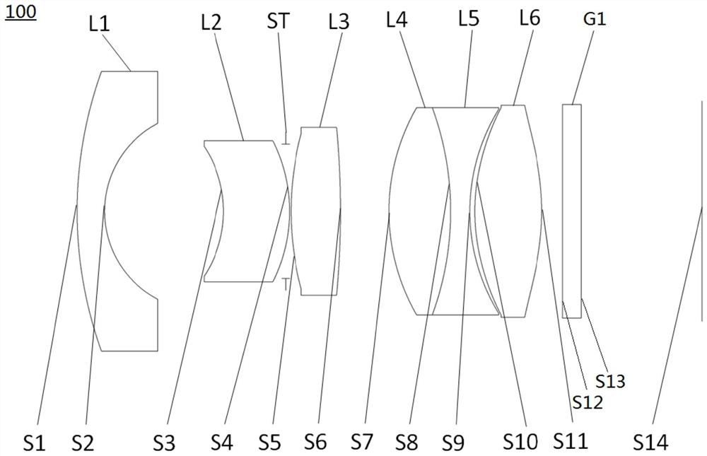
[0061] see figure 1 , which is a schematic structural view of the optical imaging lens 100 provided by the first embodiment of the present invention, the optical imaging lens 100 includes in sequence from the object side to the imaging surface along the optical axis: a first lens L1, a second lens L2, and a stop ST , the third lens L3, the fourth lens L4, the fifth lens L5, the sixth lens L6, and the filter G1;

[0062] The first lens L1 has negative refractive power, the object side S1 of the first lens L1 is a convex surface, and the image side S2 of the first lens L1 is a concave surface;

[0063] The second lens L2 has a negative refractive power, the object side S3 of the second lens L2 is a concave surface, and the image side S4 of the second lens L2 is a convex surface;

[0064] The stop ST is disposed between the second lens L2 and the third lens L3;

[0065] The third lens L3 has a positive refractive power, and both the object side S5 and the image side S6 of the t...

no. 2 example

[0081] The structure of the optical imaging lens provided by the second embodiment of the present invention is substantially the same as that of the optical imaging lens 100 in the first embodiment, except that the parameters such as the radius of curvature of each lens are different.

[0082] The relevant parameters of each lens in the optical imaging lens according to the second embodiment of the present invention are shown in Table 3.

[0083] table 3

[0084]

[0085]

[0086] The parameters of each lens aspheric surface in this embodiment are shown in Table 4.

[0087] Table 4

[0088]

[0089] Please refer to Figure 5 , Figure 6 and Figure 7 , respectively show the field curvature curve diagram, f-θ distortion diagram and MTF curve diagram of the optical imaging lens in the second embodiment. From Figure 5 It can be seen from the figure that the field curvature of the meridional image plane and sagittal image plane is controlled within ±0.04mm, indicat...

no. 3 example

[0095] see Figure 8 The third embodiment of the present invention provides an imaging device 200, and the imaging device 200 may include an imaging element 210 and the optical imaging lens (such as the optical imaging lens 100) in any of the above embodiments. The imaging element 210 may be a CMOS (Complementary Metal Oxide Semiconductor, Complementary Metal Oxide Semiconductor) image sensor, and may also be a CCD (Charge Coupled Device, Charge Coupled Device) image sensor.

[0096] The imaging device 200 may be a vehicle monitoring device, a drone, a panoramic camera, or any other form of electronic device loaded with an optical imaging lens.

[0097] The imaging device 200 provided in this embodiment includes the optical imaging lens in any of the above embodiments. Since the optical imaging lens has the advantages of high resolution, large imaging surface, large aperture, and good thermal stability, the imaging device 200 has high resolution. , large imaging surface, larg...


PUM


Abstract

The invention discloses an optical imaging lens and an imaging device. The optical imaging lens comprises in sequence from the object side to the imaging surface along the optical axis: a first lens, a second lens, a diaphragm, a third lens, a fourth lens, and a fifth lens. Lens, sixth lens and optical filter; the first lens is a meniscus lens with negative power, its object side is convex, and its image side is concave; the second lens has negative power, its object side is concave , the image side is convex; the diaphragm is set between the second lens and the third lens; the third lens has positive power, and its object side and image side are convex; the fourth lens has positive power, and its object side and The image side is convex; the fifth lens has negative power, and the object side and the image side are concave; the sixth lens has positive power, and the object side and the image side are convex. The optical imaging lens provided by the invention has the characteristics of super high resolution, good thermal stability, large aperture, convenient assembly and the like.

Description

technical field [0001] The invention relates to the technical field of imaging lenses, in particular to an optical imaging lens and imaging equipment. Background technique [0002] With the development of autonomous driving technology, ADAS (Advanced Driver Assistant System, Advanced Driver Assistance System) has become the standard configuration of automobiles; among them, the on-board camera lens, as a key component of ADAS, can sense the road conditions around the vehicle in real time and realize forward collision The performance of functions such as early warning, lane departure warning, and pedestrian detection directly affects the safety factor of ADAS. Therefore, the performance requirements of on-board camera lenses are getting higher and higher. [0003] The ADAS system has extremely high requirements on the vehicle-mounted lens. First, it needs to have strong light transmission ability and be able to adapt to changes in light and shade of the external environment. ...

Claims


Application Information

Patent Timeline
Patent Type & Authority Patents(China)
IPC IPC(8): G02B13/00G02B13/06G02B13/18
CPCG02B13/0045G02B13/006G02B13/06G02B13/18G02B9/64
Inventor 张歆越王克民曾吉勇
Owner JIANGXI LIANCHUANG ELECTRONICS CO LTD
Why Eureka
Try Eureka