Flow heat transfer and automatic control research platform and method

A platform and temperature sensor technology, applied in the testing of machine/structural components, instruments, electrical digital data processing, etc., can solve the problems of non-repeatability, difficult to accurately control the cooling process, and low efficiency.

Pending Publication Date: 2021-03-12
INST OF HIGH ENERGY PHYSICS CHINESE ACADEMY OF SCI
View PDF0 Cites 3 Cited by
  • Summary
  • Abstract
  • Description
  • Claims
  • Application Information

AI Technical Summary

Problems solved by technology

[0004] In order to overcome the shortcomings of the existing large-scale low-temperature system, which is difficult to accurately control the cooling process of the cooling equipment that is far away from the cold source, and the existing manual control method is low in efficiency and does not have repeatability, the present invention provides a flexible and economical small flow The heat transfer

Method used


Image

  • Flow heat transfer and automatic control research platform and method
  • Flow heat transfer and automatic control research platform and method
  • Flow heat transfer and automatic control research platform and method

Examples


Embodiment Construction

[0034] The present invention will be described in further detail below in conjunction with the accompanying drawings.

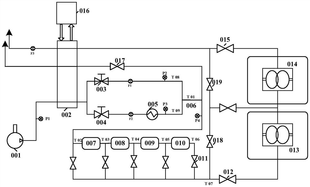
[0035] The schematic flow chart of the flow heat transfer and automatic control research platform of the present invention is as follows figure 1 shown in figure 1 Medium, mainstream working medium: air; pressure source: mobile screw air compressor (1.3MPa); heating method: electric heater; cooling method: water chiller + water / air shell-and-tube heat exchanger (cooling water tower); heat insulation Method: aluminum silicate cotton; pipe: DN25 304 stainless steel electropolished tube, which is a long spiral type, wrapped with heat insulating material; pipe connection method: welding and flange, temperature measurement method: PT100 thermal resistance; pressure measurement method: pressure sensor and differential pressure sensor; flow measurement method: vortex flowmeter*2+mass flowmeter*1; measurement and control method: PC upper computer+PLC to control the ...


PUM


Abstract

The invention discloses a flow heat transfer and automatic control research platform and method. A cooling water tower in the platform is connected with a water chilling unit; the cooling water toweris provided with two output ends and used for dividing gas in the cooling water tower into two paths, one path simulates high-pressure low-temperature gas in the refrigerating machine with high-pressure normal-temperature gas through a first electromagnetic regulating valve, and the other path simulates high-pressure normal-temperature gas in the refrigerating machine with high-pressure heating gas through a second electromagnetic regulating valve and an electric heater in sequence; high-pressure normal-temperature gas and high-pressure heating gas are heated and mixed through a pipe section,and the mixed gas passes through a first long spiral pipe, a second long spiral pipe, a third long spiral pipe and a fourth long spiral pipe which are connected in series; the gas coming out of the fourth long spiral pipe sequentially passes through a first switch valve and a second switch valve to reach first superconducting equipment and second superconducting equipment which are connected in series, the first superconducting equipment and the second superconducting equipment are used for absorbing heat in the gas to enable the temperature of the equipment to rise, and the temperature risingeffect is used for simulating the cooling process of the superconducting equipment.

Description

technical field [0001] The invention relates to the field of flow heat transfer and automatic control, in particular to an experimental platform and method for simulating flow heat transfer phenomena and automatic control strategies in the cooling / rewarming process of superconducting equipment. Background technique [0002] In recent years, the country's new large scientific projects (PAPS, HEPS, SHINE, CIADS, HIAF, CEPC, etc.) have all adopted large-scale helium cryogenic systems to provide cooling capacity for superconducting equipment. Limited by engineering site planning and vibration requirements, etc., the distance between the cooling source and the actual cooling equipment (superconducting cavity or superconducting magnet) is usually long (on the order of hundreds of meters), and the cooling equipment cannot withstand too much thermal stress. Higher requirements are placed on the cooling rate. Existing cooling methods usually use high-pressure normal-temperature gas ...

Claims


Application Information

Patent Timeline
IPC IPC(8): G06F30/20G01M99/00G06F113/08G06F119/08
CPCG01M99/002G01M99/008G06F30/20G06F2113/08G06F2119/08
Inventor 李梅常正则葛锐朱柯宇韩瑞雄李少鹏孙良瑞张洁浩桑民敬叶瑞张祥镇徐妙富
Owner INST OF HIGH ENERGY PHYSICS CHINESE ACADEMY OF SCI
Why Eureka
Try Eureka