
Deicing circuit and deicing device

A technology of circuits and capacitors, applied in the field of maintenance of high-voltage lines, to improve efficiency and overcome the lag of deicing operations

Pending Publication Date: 2021-03-12
STATE GRID ANHUI ULTRA HIGH VOLTAGE CO +1
View PDF0 Cites 0 Cited by
  • Summary
  • Abstract
  • Description
  • Claims
  • Application Information

AI Technical Summary

Problems solved by technology

However, this method needs to transport the deicing vehicle to the vicinity of the deicing line section, and there is a certain lag

Method used


Image

  • Deicing circuit and deicing device
  • Deicing circuit and deicing device
  • Deicing circuit and deicing device

Examples


Embodiment Construction

[0047] The specific implementation manners of the embodiments of the present invention will be described in detail below in conjunction with the accompanying drawings. It should be understood that the specific implementation manners described here are only used to illustrate and explain the implementation manners of the present invention, and are not intended to limit the implementation manners of the present invention.

[0048] In the embodiments of the present invention, unless stated otherwise, the used orientation words such as "up, down, top, bottom" are usually for the directions shown in the drawings or for vertical, vertical or The term used to describe the mutual positional relationship of each component in terms of the direction of gravity.

[0049] In addition, if there are descriptions involving "first", "second" and so on in the embodiments of the present invention, the descriptions of "first", "second" and so on are only for descriptive purposes, and should not b...


PUM


Abstract

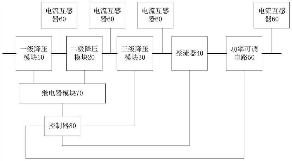
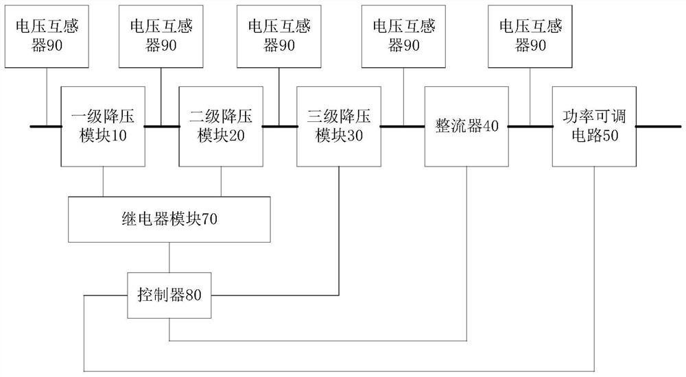
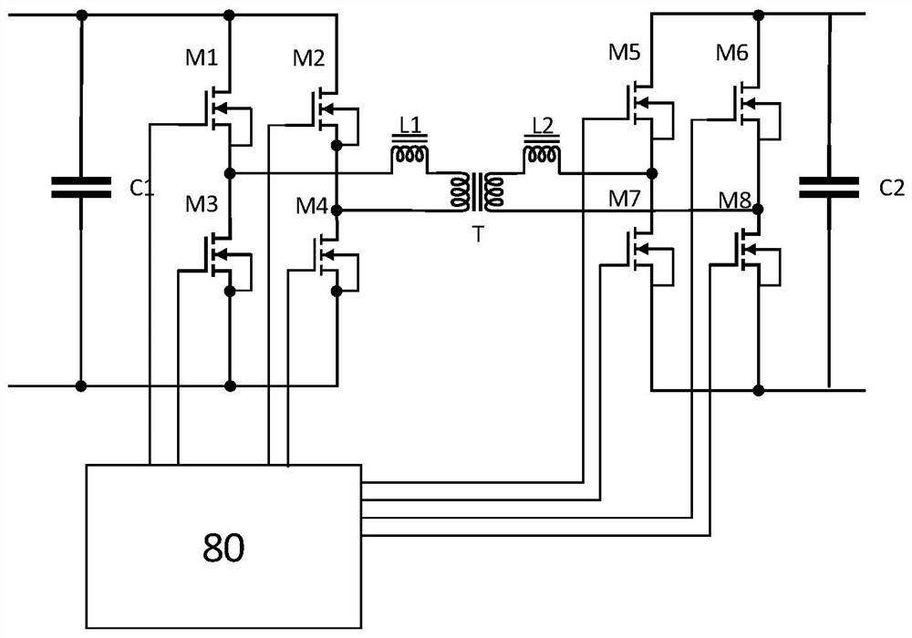
The embodiment of the invention provides a deicing circuit and a deicing device, and belongs to the technical field of maintenance of high-voltage lines. The deicing circuit comprises a first-stage voltage reduction module, a second-stage voltage reduction module, a third-stage voltage reduction module, a rectifier, a power adjustable circuit, at least four current transformers, a relay module anda controller. The controller is used for receiving current values measured by the current transformers. The relay module is used for controlling the work of the first-stage voltage reduction module and the second-stage voltage reduction module; and the third-stage voltage reduction module, the rectifier and the power adjustable circuit are controlled to work. According to the deicing circuit andthe deicing device provided by the invention, the control instruction of the control center is remotely received, the power is directly taken through the high-voltage line, the original high-voltage power is converted into high-current low-voltage power, and the deicing operation of the high-voltage line is completed according to a resistance heat principle; the technical defect of deicing operation hysteresis caused by dependence on a deicing vehicle in the prior art is overcome, and the deicing efficiency of the high-voltage line is improved.

Description

technical field [0001] The invention relates to the technical field of maintenance of high-voltage lines, in particular to a deicing circuit and a deicing device. Background technique [0002] High-voltage power transmission technology is one of the most commonly used power transmission strategies in the electric power field. Through high-voltage lines, the purpose of power transmission with minimum line loss can be achieved under the high-power strategy of high voltage and low current. Since the high-voltage line is in a high-voltage state, in order to avoid forming a capacitor effect with the ground, it needs to be installed in the sky at a certain height. [0003] In some areas in the north, due to the influence of bad weather such as snowfall, snow and ice will appear on the high-voltage lines, which will lead to an increase in the lateral tension on the high-voltage lines, which may seriously cause problems such as line breaks. produce. In the prior art, for the deici...

Claims


Application Information

Patent Timeline
IPC IPC(8): H02M7/04H02M3/335H02G7/16H02G1/02
CPCH02G1/02H02G7/16H02M3/33576H02M7/04
Inventor 焦震杜鹏章海斌熊泽群宁彦汪太平沈杨占晓友陈旭东施雯胡茂亮张冬晛朱涛焦玉平尹悦华超
Owner STATE GRID ANHUI ULTRA HIGH VOLTAGE CO
Features
  • Generate Ideas
  • Intellectual Property
  • Life Sciences
  • Materials
  • Tech Scout
  • Unparalleled Data Quality
  • Higher Quality Content
  • 60% Fewer Hallucinations
Learn More