
Device and method for realizing alignment tracking wireless optical communication by using communication optical peripheral part

A technology of wireless optical communication and peripheral parts, applied in the field of wireless optical communication, can solve the problems of increasing the weight, volume and power consumption of the device, weakening the optical signal, and large loss of optical energy, and achieves improved communication effects and alignment and tracking accuracy. High, easy-to-install effect

Pending Publication Date: 2021-03-12
长春光客科技有限公司
View PDF1 Cites 6 Cited by
  • Summary
  • Abstract
  • Description
  • Claims
  • Application Information

AI Technical Summary

Problems solved by technology

However, since the communication light-receiving optical system can only focus a part of the received light signal on the photodetector with a scale of microns, the loss of light energy is already relatively large. The signal is further weakened, and it has to be compensated by increasing the emitted light intensity, which also increases the weight, volume and power consumption of the device

Method used


Image

  • Device and method for realizing alignment tracking wireless optical communication by using communication optical peripheral part
  • Device and method for realizing alignment tracking wireless optical communication by using communication optical peripheral part
  • Device and method for realizing alignment tracking wireless optical communication by using communication optical peripheral part

Examples


Embodiment Construction

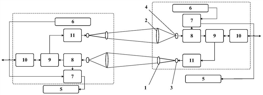
[0012] The following is a further description of the alignment and tracking wireless optical communication device utilizing the peripheral part of the communication light of the present invention.

[0013] The emission optical system 1 is played by a plano-convex lens with an aperture of 5 mm and a focal length of 5 mm.

[0014] The receiving optical system 2 is served by a single plano-convex lens with an aperture of 10mm and a focal length of 5mm.

[0015] The laser diode 3 is a DFB laser diode with a light emission wavelength of 1550 nm and a flat light emitting end face.

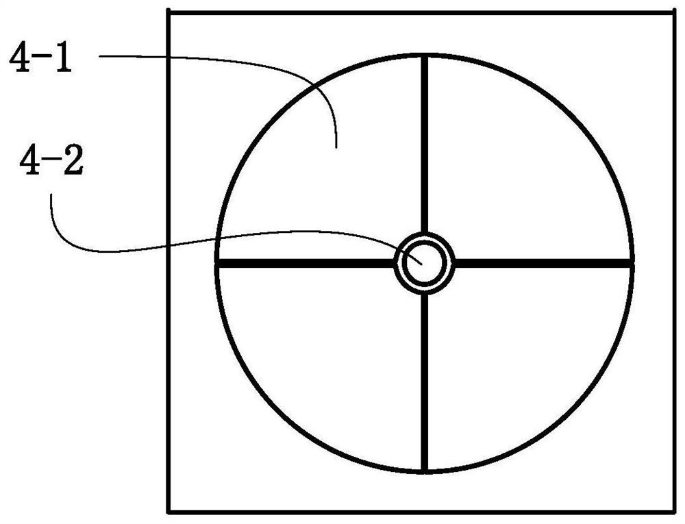
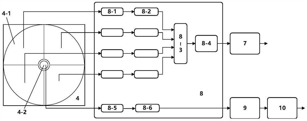
[0016] The multi-quadrant photodetector 4 is equipped with four alignment and tracking detectors 4-1 and one communication detector 4-2, and the alignment and tracking detector 4-1 and the communication detector 4-2 are performed by the same photoelectric device. Such as a PIN photodiode or an APD photodiode, the spectral response range is 900-1700nm; the geometric scale of the alignment tracking detect...


PUM

PropertyMeasurementUnit
Radiusaaaaaaaaaa
Diameteraaaaaaaaaa

Abstract

The invention discloses a wireless optical communication device and method for achieving alignment tracking through a communication light peripheral part, and belongs to the technical field of wireless optical communication. An existing gigabit rate wireless optical communication system is large in size, weight and power consumption. In the multi-quadrant photoelectric detector of the device, a plurality of same alignment tracking detectors surround a communication detector to form an integral photosensitive surface; in the detection receiving module, an alignment tracking transimpedance amplifier and an alignment tracking limiting amplifier are connected to form amplification circuits, the multiple amplification circuits are parallel and are connected with a multi-channel A / D acquisitionchip, and the multi-channel A / D acquisition chip is further connected with an arithmetic unit. And between the multi-quadrant photoelectric detector and the detection receiving module, each alignmenttracking detector is connected with the input end of the alignment tracking transimpedance amplifier in each amplification circuit. According to the method, alignment tracking control signals are extracted by a plurality of alignment tracking detectors, communication electric signals are extracted by a communication detector, and communication and alignment tracking are synchronous.

Description

technical field [0001] The invention relates to a wireless optical communication device and method for realizing alignment and tracking by using the peripheral part of communication light, and belongs to the technical field of wireless optical communication. Background technique [0002] In a wireless optical communication system, the communication subsystem and the capture alignment tracking subsystem, as well as the capture alignment tracking subsystem, do not have a complete common-aperture structure, so it is necessary to ensure that multiple optical axes are precisely coaxial, including: 1 , Capture / coarse tracking and detection boresight are coaxial; 2, precise tracking and detection are boresight coaxial; 3, communication boresight are coaxial. Not only the structure is complex, but also the overall design, processing and assembly of the wireless optical communication system are very difficult, and the cost cannot be reduced. [0003] Therefore, a Chinese patent appl...

Claims


Application Information

Patent Timeline
IPC IPC(8): H04B10/114H04B10/40
CPCH04B10/114H04B10/40
Inventor 倪小龙于信董喆朱旭刘智
Owner 长春光客科技有限公司
Learn More