Supercharge Your Innovation With Domain-Expert AI Agents!

Automatic loading and unloading equipment and automatic cargo loading and unloading method

A technology of automatic loading and unloading and equipment, which is applied in the direction of loading/unloading, transportation and packaging, conveyor objects, etc. It can solve the problems of inability to dock with docks, etc., and achieve the effects of not being easily damaged, long service life, and improving the service life

Pending Publication Date: 2021-03-16
FU TAI HUA IND SHENZHEN
View PDF0 Cites 1 Cited by
  • Summary
  • Abstract
  • Description
  • Claims
  • Application Information

AI Technical Summary

Problems solved by technology

[0004] In view of the above situation, it is necessary to provide an automatic loading and unloading equipment and an automatic loading and unloading method to solve the problem that the transport device cannot be docked at the dock

Method used


Image

  • Automatic loading and unloading equipment and automatic cargo loading and unloading method
  • Automatic loading and unloading equipment and automatic cargo loading and unloading method
  • Automatic loading and unloading equipment and automatic cargo loading and unloading method

Examples


Embodiment 1

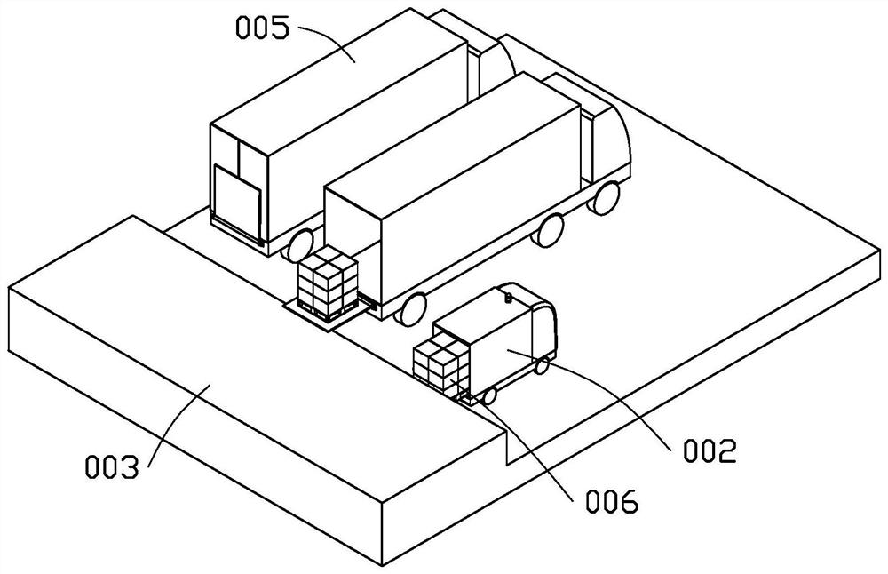
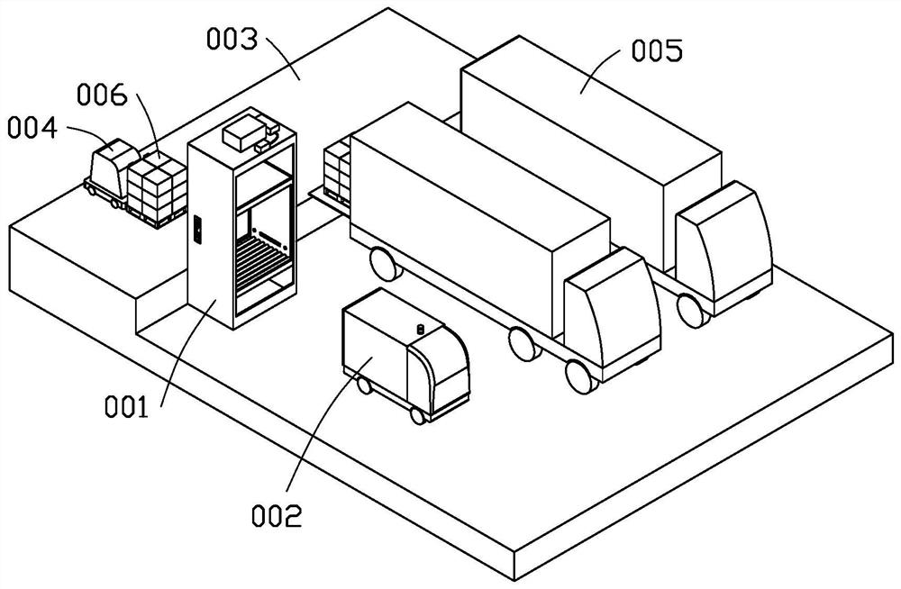
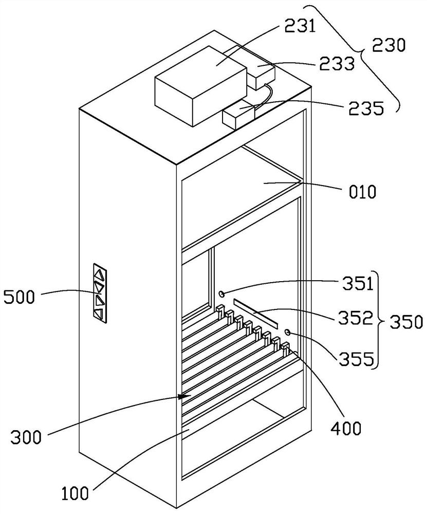
[0130] see figure 2 and image 3 , the first embodiment of the present application provides an automatic loading and unloading device 001, which is used for transferring goods 006 between unloading positions and loading positions with height differences such as wharf 003. This automatic loading and unloading device 001 includes a lifting plate 100 and a transmission device. The lifting plate 100 has a load-bearing surface 101 for carrying goods 006. The transmission device transmits the goods 006 on the load-bearing surface 101 between the unloading position and the loading position with a height difference. Displacement, the transmission device includes a lifting part 200 and a traverse part 300; the lifting part 200 includes an outer frame 210 and a lifting drive device 230, the lifting plate 100 is accommodated in the outer frame 210, and the driving end of the lifting drive device 230 drives the lifting plate 100 outside The inner frame 210 is raised and lowered, and the...

Embodiment 2

[0156] see Figure 15 , the second embodiment of the present application provides an automatic loading and unloading method, using the transportation device 002 and the automatic loading and unloading equipment 001 provided in Embodiment 1 to realize unloading of the cargo 006 on the wharf 003 and loading the cargo 006 into the transportation device 002 ,include:

[0157] S101 : The transportation device 002 initiates a docking command to the wireless communication unit 235 electrically connected to the lifting driving device 230 .

[0158] S102: The lifting drive device 230 drives the lifting plate 100 to rise to the height of the wharf 003.

[0159] S103: The wireless communication unit 235 sends an instruction to start loading to the transportation device 002 and the forklift 004.

[0160] S104: The forklift 004 sends the goods 006 on the wharf 003 to the carrying surface 101 and contacts the traverse unit 300, such as Figure 9 , Figure 10 and Figure 11 shown.

[0...


PUM


Abstract

Automatic loading and unloading equipment is used for loading and unloading cargoes on a wharf and comprises a lifting plate and a transmission device, the lifting plate is provided with a bearing surface used for bearing the cargoes, the transmission device conveys the cargoes on the bearing surface to move between an unloading position and a loading position which have height difference, and thetransmission device comprises a lifting part and a transverse moving part; the lifting part comprises an outer frame and a lifting driving device, the lifting plate is contained in the outer frame, the driving end of the lifting driving device drives the lifting plate to ascend and descend in the outer frame, and the outer frame is provided with a first opening facing the wharf and a second opening deviating from the wharf; and the transverse moving part is arranged on the bearing face and used for driving cargoes to enter or be conveyed out of the bearing face. By means of the automatic loading and unloading equipment, the cargoes on the wharf can be stably transported into a carriage at the height different from that of the wharf, and after the cargoes are transported to the height of the carriage, the cargoes are transported out of the lifting plate through the transverse moving part. The invention further provides an automatic cargo loading and unloading method.

Description

technical field [0001] The application relates to an automatic loading and unloading device and an automatic loading and unloading method. Background technique [0002] The existing plant loading and unloading wharf 003 is mainly used for the docking of large and medium-sized trucks, such as figure 1 shown. Usually the wharf 003 is higher than the ground of the vehicle parking area. After the manned truck 005 approaches the wharf 003, the tail lift is lowered so that the tail lift leans against the wharf 003, and the docking loading and unloading of the truck and the wharf 003 is realized by the lifting of the tail lift. [0003] After the transportation device 002 is adopted, due to the small size of the transportation device 002 and the low chassis, the height of the compartment is lower than that of the wharf 003, and the pallet cargo 006 cannot be automatically loaded and unloaded between the wharf 003 and the transportation device 002. Generally, it is necessary to man...

Claims


Application Information

Patent Timeline
Patent Type & Authority Applications(China)
IPC IPC(8): B65G67/04B65G47/90
CPCB65G47/90B65G67/04
Inventor 李鸿钧谭谊诚
Owner FU TAI HUA IND SHENZHEN
Features
  • R&D
  • Intellectual Property
  • Life Sciences
  • Materials
  • Tech Scout
  • Unparalleled Data Quality
  • Higher Quality Content
  • 60% Fewer Hallucinations
Learn More