Supercharge Your Innovation With Domain-Expert AI Agents!

Motor rotor axial vibration compensation mechanism and center wire passing method

A technology of motor rotor and compensation mechanism, which is applied in the fields of earth-moving drilling, automatic control system for drilling, driving device for drilling in wellbore, etc., can solve the problems of poor reliability, low transmission efficiency, poor contact quality, etc. Effect of Rotational Torque and Drilling ROP

Active Publication Date: 2021-03-19
BC P INC CHINA NAT PETROLEUM CORP +2
View PDF7 Cites 0 Cited by
  • Summary
  • Abstract
  • Description
  • Claims
  • Application Information

AI Technical Summary

Problems solved by technology

[0006] The main purpose of the present invention is to solve the technical problems of poor reliability, poor contact quality, and low transmission efficiency in the prior art, and to provide a motor rotor axial vibration compensation mechanism and a center line passing method

Method used


Image

  • Motor rotor axial vibration compensation mechanism and center wire passing method
  • Motor rotor axial vibration compensation mechanism and center wire passing method
  • Motor rotor axial vibration compensation mechanism and center wire passing method

Examples


Embodiment 1

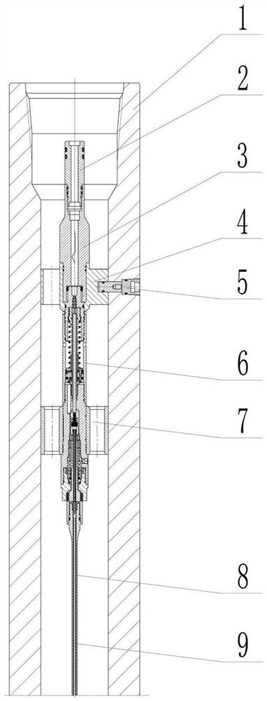
[0035] This embodiment firstly provides a slip ring connection assembly, its structure is as follows figure 1 shown.

[0036] The slip ring connection assembly includes a slip ring assembly outer shell 1, a socket joint 2, a transition positioning joint 3, a slip ring assembly positioning centralizer 4, a positioning pin 5, a slip ring assembly 6, a slip ring centralizer 7, flex shaft 8, conductive rod 9, figure 1 The wire passing way of the formed slip ring assembly can convert the rotating wires in the rotor 21 and the flexible shaft 8 into fixed wire connections.

[0037] Wherein, the slip ring connection assembly includes a slip ring assembly outer shell 1, which is provided with a transition positioning joint 3 and a slip ring assembly 7 respectively fixed by a slip ring assembly positioning centralizer 4 and a slip ring centralizer 7 A flexible shaft 8 is arranged at the lower end of the slip ring assembly 7, and a flexible shaft conductive rod 9 is arranged inside the...

Embodiment 2

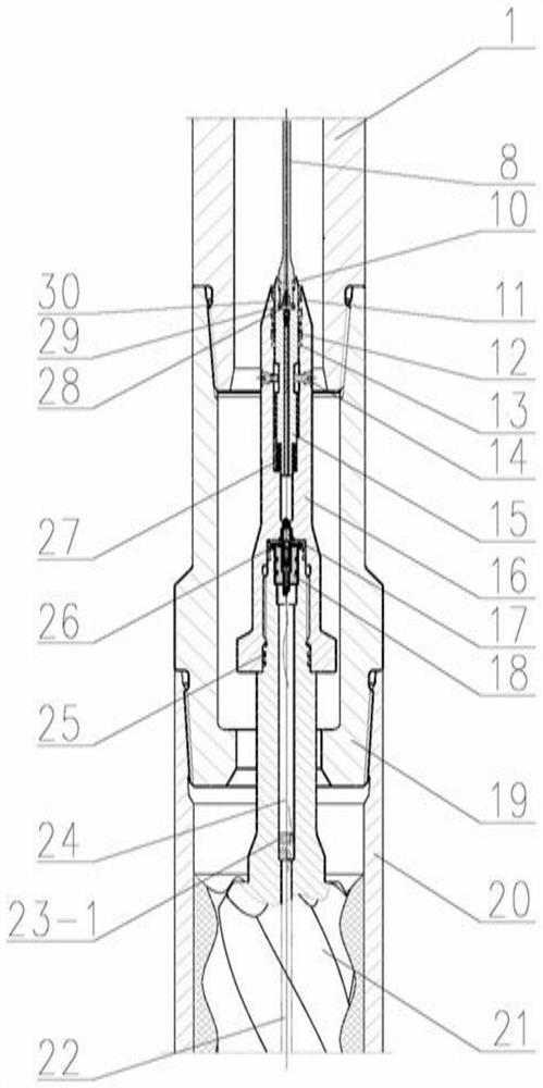
[0039] Among the various existing over-the-wire motor technologies, some of the methods and devices used for screw over-the-wire connection communication use a slip ring connection structure, and some use wireless coupling communication. Affected by tool vibration and rotor axial position changes when the downhole screw is working, the slip ring structure has the problems of difficult to guarantee sealing and poor contact quality, and the wireless coupling transmission method has problems of poor reliability and low transmission efficiency. Aiming at these problems, this embodiment provides a wire passing motor assembly, its structure is as follows figure 2 shown.

[0040] The function of the wire-passing motor assembly is to eliminate the axial vibration or floating generated by the motor rotor 21, so as to ensure that the central wire passing through here is connected, so as not to tear the wire.

[0041] The wire passing motor assembly includes a flexible shaft seal 10, a...

Embodiment 3

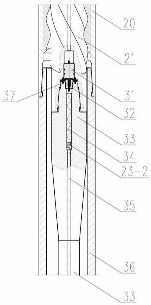
[0053] In the prior art, the main line of the over-the-line cardan shaft is unstable, the line has poor anti-vibration ability, and the conductive plug and socket are in poor contact, which leads to problems such as large line transmission resistance, line heating, and unstable connection.

[0054] Aiming at these problems, this embodiment provides a line-passing cardan shaft assembly, the structure of which is as follows Figure 3-4 shown. The over-the-line cardan shaft assembly includes: the conductive pin 31 under the rotor, the conductive socket 32 ​​on the flexible shaft, the power flexible shaft 33, the central wire 34 of the power flexible shaft, the winding seat 23-2 of the flexible shaft, the power flexible shaft wire 35. The outer casing of the flexible shaft 36, the flexible shaft sealing ring 37, through the lower conductive pin 31 of the rotor, the lower sealing ring of the flexible shaft 38, the lower conductive pin 39 of the flexible shaft, the transition socket...


PUM


Abstract

The invention relates to a vibration compensation mechanism and a wire passing method, belongs to the technical field of drilling, and particularly relates to a motor rotor axial vibration compensation mechanism and a center wire passing method. The device comprises an anti-drop tensile joint. and an axial floating shaft which is arranged in the anti-drop tensile joint and can move in the axial direction of the anti-drop tensile joint . The upper end and the lower end of the axial floating shaft are electrically connected with a transmission medium in the flexible shaft and an upper conductiveconnecting device on a rotor respectively. According to the vibration compensation mechanism and the wire passing method, the problem that a power source wire and a signal wire penetrate through thescrew motor is solved in a center wire passing mode, simultaneous transmission of the power and the signal is achieved, the vibration compensation mechanism and the wire passing method are suitable for a rotary steering system and other underground control detection systems, and communication and power transmission of wires can be achieved through the screw motor.

Description

technical field [0001] The invention relates to a vibration compensating mechanism and a threading method, belonging to the technical field of drilling, in particular to a motor rotor axial vibration compensating mechanism and a center passing method. Background technique [0002] The central over-the-line synergistic screw motor has the function of simultaneous signal and power transmission, and can increase the power and speed of the rotary steering system and increase the drilling speed of the drilling machine. Bottom and surface signals can be transmitted through the center through-line synergistic screw motor, and the power generated by the generator connected to the upper end of the center through-line synergistic screw motor can be transmitted to the lower end of the synergistic screw motor through the center through-line synergistic motor rotary steerable system. The geometric parameters and geological parameters collected by the sensors of the rotary steerable syst...

Claims


Application Information

Patent Timeline
Patent Type & Authority Applications(China)
IPC IPC(8): E21B4/02E21B17/02E21B44/00H01R24/00
CPCE21B4/02E21B17/023E21B44/00H01R24/00
Inventor 盛利民王鹏窦修荣范锦辉贾衡天洪迪峰管康彭浩陈晨于兴胜陈业生张磊樊懿锋
Owner BC P INC CHINA NAT PETROLEUM CORP
Features
  • R&D
  • Intellectual Property
  • Life Sciences
  • Materials
  • Tech Scout
  • Unparalleled Data Quality
  • Higher Quality Content
  • 60% Fewer Hallucinations
Learn More