Oil well acidification process and device for increasing oil-gas well yield

A technology for acidizing oil wells and oil and gas wells, which is applied in wellbore/well components, drilling compositions, chemical instruments and methods, etc., and can solve problems such as long construction period, corrosion of production equipment such as downhole pipe strings, and acid pollution , to achieve the effect of solving oil layer blockage, convenient construction and reducing acid content

Active Publication Date: 2021-03-19
西安石油大油气科技有限公司
View PDF11 Cites 8 Cited by
  • Summary
  • Abstract
  • Description
  • Claims
  • Application Information

AI Technical Summary

Problems solved by technology

[0003] Currently commonly used acidification technologies are divided into conventional three-stage and continuous acidification. The conventional acidification method usually requires liquid drainage after acidification, the construction period is long, and the discharged acid liquid is easy to cause pollution, while continuous acidification does not require flowback but is easy to Corrosion caused by production equipment such as downhole pipe strings

Method used


Image

  • Oil well acidification process and device for increasing oil-gas well yield
  • Oil well acidification process and device for increasing oil-gas well yield
  • Oil well acidification process and device for increasing oil-gas well yield

Examples


Embodiment 1

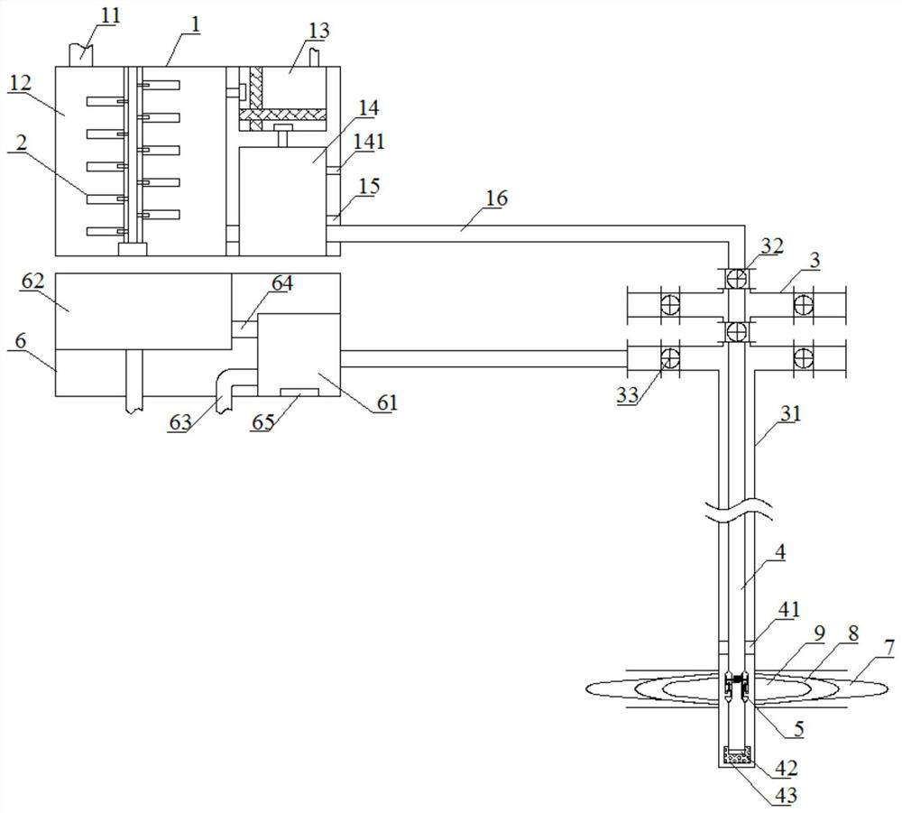
[0045] Such as figure 1 Shown, a kind of oil well acidizing process for improving oil and gas well production comprises the following steps:

[0046] S1 Acidizing Pretreatment: Pull out the production string in the test well with a body length of 1387m, run it into the well cleaning string, and perform a positive flushing and a backwashing. It is injected into the casing and returned. Backwashing is to inject the flushing fluid from the casing and return to the flushing string. The volume of the flushing fluid is 12m 3 , the mass ratio of the components of the well flushing fluid is surfactant: fluid loss control agent: octylphenol polyoxyethylene ether: water = 4:2:3:91, and the well flushing string is pulled out after the well flushing is completed;

[0047] S2 note pre-acid solution 7: such as Figure 10 As shown, the acidizing string 4 with a packer 41 is lowered. The packer 41 is a commercially available Y241-115 packer. The device 41 is sealed, and the pre-acid liquid...

Embodiment 2

[0061] This embodiment is basically the same as Embodiment 1, except that the injection speeds of the pre-acid solution 7, the reaction acid solution 8, and the neutralizing agent 9 are different, specifically:

[0062] Note pre-acid solution 7: injection speed is 0.35m 3 / min;

[0063] Injection reaction acid solution 8: the injection speed is 0.55m 3 / min;

[0064] Note neutralizer 9: injection speed is 0.2m 3 / min.

Embodiment 3

[0066] This embodiment is basically the same as Embodiment 1, except that the injection speeds of the pre-acid solution 7, the reaction acid solution 8, and the neutralizing agent 9 are different, specifically:

[0067] Note the pre-acid solution 7: the injection speed is 0.5m 3 / min;

[0068] Injection reaction acid solution 8: injection speed is 0.7m 3 / min;

[0069] Note neutralizer 9: injection speed is 0.3m 3 / min.


PUM


Abstract

The invention discloses an oil well acidification process and device for increasing oil-gas well yield. The oil well acidification device comprises an acid liquid tank and a waste liquid tank, whereina stirring tank is arranged in the acid liquid tank, a stirring device is arranged in the stirring tank, an acidification pipe column penetrates through a wellhead device and then extends into the bottom of a casing pipe, a nozzle is arranged at the bottom of the acidification pipe column, and pulse supercharging devices are arranged on the two sides of the acidification pipe column above the nozzle; and the waste liquid tank is connected with a liquid outlet of the wellhead device. The acidification process comprises the following steps that S1, acidification pretreatment is conducted; S2, preposed acid liquid is injected; S3, reaction acid liquid is injected; and S4, a neutralizer is injected in a pulse pressurization mode, so that the acid liquid enters an oil layer in a fluctuation mode, the swept area is enlarged, the injection effect of the acid liquid is effectively enhanced, residual acid liquid is neutralized in sections at the bottom of a well, the content of the acid liquidin flowback fluid is reduced, components of preposed acid liquid, reaction acid liquid and the neutralizer are optimized, the problem of oil layer blockage can be effectively solved, and the purposeof increasing the yield is achieved.

Description

technical field [0001] The invention relates to the technical field of oil well acidizing production increase, in particular to an oil well acidizing process and device for increasing the production of oil and gas wells. Background technique [0002] Acidizing is a means of adding acidic reagents to oil wells in oilfield production to increase oil well production and recovery. Porosity and permeability, enhance the fluidity of crude oil in formation pores. [0003] Currently commonly used acidification technologies are divided into conventional three-stage and continuous acidification. The conventional acidification method usually requires liquid drainage after acidification, the construction period is long, and the discharged acid solution is easy to cause pollution, while continuous acidification does not require flowback but is easy to Downhole pipe strings and other production equipment cause corrosion. [0004] Therefore, it is necessary to provide an optimized acidiz...

Claims


Application Information

Patent Timeline
Patent Type & Authority Applications(China)
IPC IPC(8): E21B43/27C09K8/74
CPCE21B43/26C09K8/74C09K2208/32
Inventor 张相春郉艳斌赵晨张鑫张国华李昂崔国威
Owner 西安石油大油气科技有限公司
Why Eureka
Try Eureka