Safe combustible gas self-pressurization container and temperature adjusting and circulating all-in-one machine thereof

A gas temperature, self-pressurization technology, applied in non-pressure vessels, gas/liquid distribution and storage, container filling methods, etc., can solve the problems of combustible gas waste, hidden safety hazards, lack of self-pressurization system, etc., to ensure safety Sexual, stressful effects

Active Publication Date: 2021-03-19
NANJING UNIV OF SCI & TECH
View PDF10 Cites 0 Cited by
  • Summary
  • Abstract
  • Description
  • Claims
  • Application Information

AI Technical Summary

Problems solved by technology

[0002] Most of the existing combustible gas storage and transportation devices lack a self-pressurization system. When the gas is released, the pressure in the container will drop rapidly as the gas is discharged, so that the remaining gas cannot be discharged due to insufficient pressure, resulting in waste of combustible gas; The current solution is to connect a set of pressurization equipment to the storage device to pressurize the combustible gas, such as the patent number "201621125322. There is a vaporization and self-pressurization device outside the LNG fuel gas storage tank. The vaporization and self-pressurization device includes a heat exchanger and an auxiliary hot water unit. The LNG fuel gas storage tank is connected to the heat exchanger through a pipeline. The LNG fuel in the fuel gas storage tank is delivered to the vaporization and self-pressurization device, and then transported back to the LNG fuel gas storage tank after heating, vaporization and pressurization, which not only increases the operation steps, but also requires external booster equipment It is easy to cause the risk of flammable gas leaking from the connection, thus bringing safety hazards

Method used


Image

  • Safe combustible gas self-pressurization container and temperature adjusting and circulating all-in-one machine thereof

Examples


Embodiment Construction

[0025] The following will clearly and completely describe the technical solutions in the embodiments of the present invention with reference to the accompanying drawings in the embodiments of the present invention. Obviously, the described embodiments are only some, not all, embodiments of the present invention. Based on the embodiments of the present invention, all other embodiments obtained by persons of ordinary skill in the art without making creative efforts belong to the protection scope of the present invention.

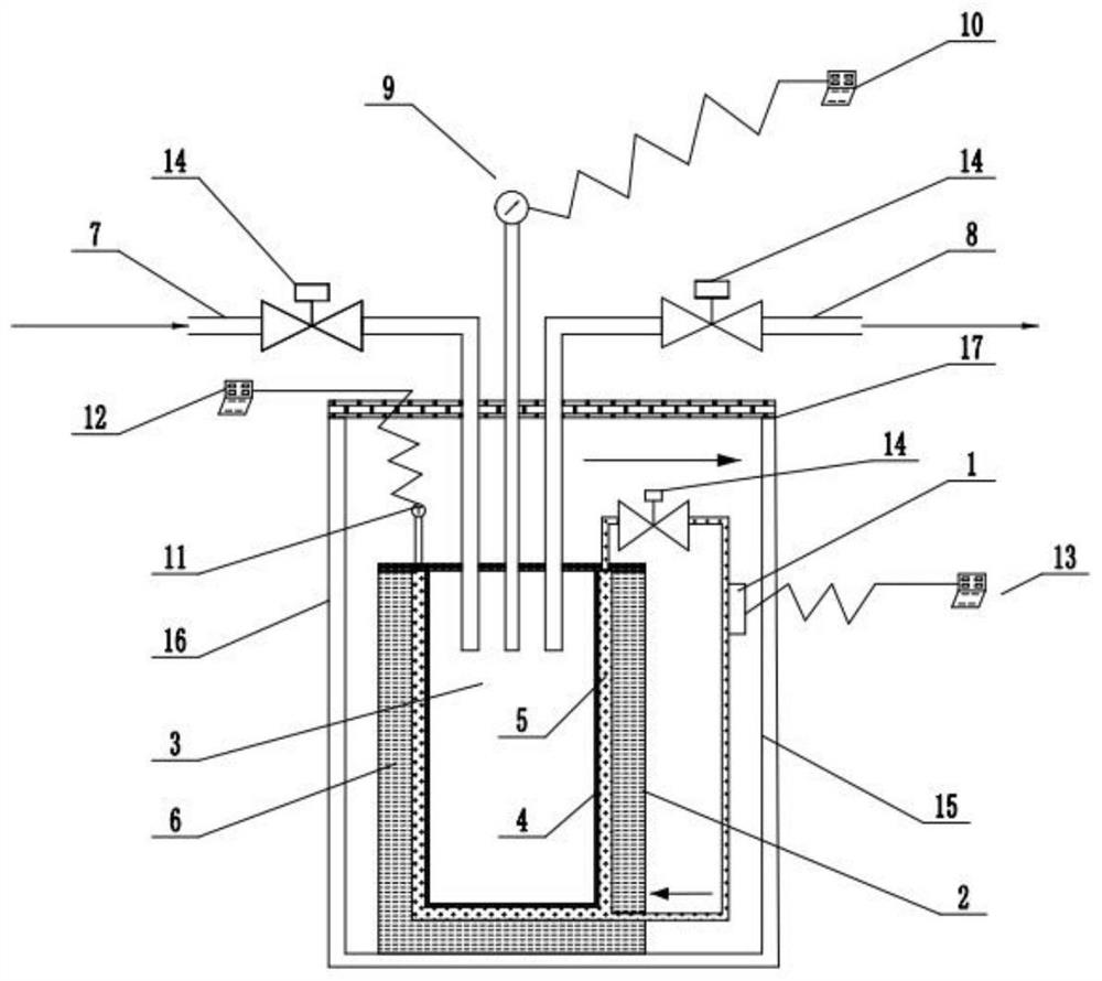
[0026] This embodiment provides a safe combustible gas self-pressurization container, such as figure 1 As shown, the self-pressurized container 2 is integrally formed by the top cover and the shell, and the shell of the self-pressurized container 2 is composed of the thin wall 4 of the container and the outer wall 6 of the container. The thin wall 4 of the container can withstand a certain gas pressure, and the outer wall 6 of the container can isolate Externa...


PUM


Abstract

The invention discloses a safe combustible gas self-pressurization container and a temperature adjusting and circulating all-in-one machine thereof, and belongs to the technical field of gas self-pressurization devices. The self-pressurization container sequentially comprises a cavity used for storing combustible gas, a container thin wall used for bearing pressure, a hollow interlayer used for containing heat conduction liquid and a container outer wall used for heat insulation from inside to outside; an air inlet pipe and an air outlet pipe which are communicated with the cavity are arrangedon the self-pressurization container; the storage and pressurization functions are integrated on the self-pressurization container; the combustible gas in the self-pressurization container is directly heated and pressurized by adjusting the temperature of the heat conduction liquid, and external pressurization equipment is not needed, so that unnecessary operation steps are omitted; and meanwhile, the combustible gas in the self-pressurization container does not need to be conveyed into the external pressurization equipment so as to be pressurized, so that the potential safety hazard of leakage at the joint of the self-pressurization container and the external pressurization equipment is avoided.

Description

technical field [0001] The invention relates to the technical field of gas self-pressurizing devices, in particular to a safe combustible gas self-pressurizing container and a temperature-regulating and circulating integrated machine thereof. Background technique [0002] Most of the existing combustible gas storage and transportation devices lack a self-pressurization system. When the gas is released, the pressure in the container will drop rapidly as the gas is discharged, so that the remaining gas cannot be discharged due to insufficient pressure, resulting in waste of combustible gas; The current solution is to connect a set of pressurization equipment to the storage device to pressurize the combustible gas, such as the patent No. "201621125322. There is a vaporization and self-pressurization device outside the LNG fuel gas storage tank. The vaporization and self-pressurization device includes a heat exchanger and an auxiliary hot water unit. The LNG fuel gas storage tan...

Claims


Application Information

Patent Timeline
Patent Type & Authority Applications(China)
IPC IPC(8): F17C3/02F17C3/04F17C13/00F17C13/02
CPCF17C3/02F17C3/04F17C13/00F17C13/025F17C13/026F17C2201/0104F17C2203/03F17C2250/043F17C2250/0631
Inventor 徐森蒋宇轩王旭吴星亮徐飞扬钱华刘大斌
Owner NANJING UNIV OF SCI & TECH
Why Eureka
Try Eureka