Electromagnetic superconducting drying oven

A drying furnace, superconducting technology, applied in drying, drying machine, drying gas arrangement, etc., can solve the problem of low utilization rate of thermal effect of electromagnetic heater, inapplicability to drying of different materials, low heat conduction efficiency of drying inner barrel, etc. problems, to achieve the effect of improving the utilization rate of thermal effect, obvious energy saving efficiency and ensuring cleanliness

Pending Publication Date: 2021-03-19
山东锦恒环保设备有限公司
View PDF1 Cites 2 Cited by
  • Summary
  • Abstract
  • Description
  • Claims
  • Application Information

AI Technical Summary

Problems solved by technology

[0004] Although the above-mentioned patents are equipped with a drying inner barrel, an electromagnetic heating coil, an electromagnetic heater, a temperature sensor and a controller, the drying heating efficiency is greatly improved, and the drying temperature of the material in the drying inner barrel can be controlled at the set temperature. Within the range, the drying treatment effect on materials has been greatly improved, but the heat conduction efficiency of the drying inner barrel is too low, the thermal effect utilization rate of the electromagnetic heater is low, and the energy waste is particularly large, which is not energy-saving, and cannot be applied to different materials. Drying, for example, dust-free materials and anaerobic materials, therefore, has relatively large limitations, so it is necessary to develop a new type of electromagnetic superconducting drying furnace to solve the deficiencies in the existing technology

Method used


Image

  • Electromagnetic superconducting drying oven
  • Electromagnetic superconducting drying oven
  • Electromagnetic superconducting drying oven

Examples


Embodiment Construction

[0025] The following will clearly and completely describe the technical solutions in the embodiments of the present invention with reference to the accompanying drawings in the embodiments of the present invention. Obviously, the described embodiments are only some, not all, embodiments of the present invention. Based on the embodiments of the present invention, all other embodiments obtained by persons of ordinary skill in the art without making creative efforts belong to the protection scope of the present invention.

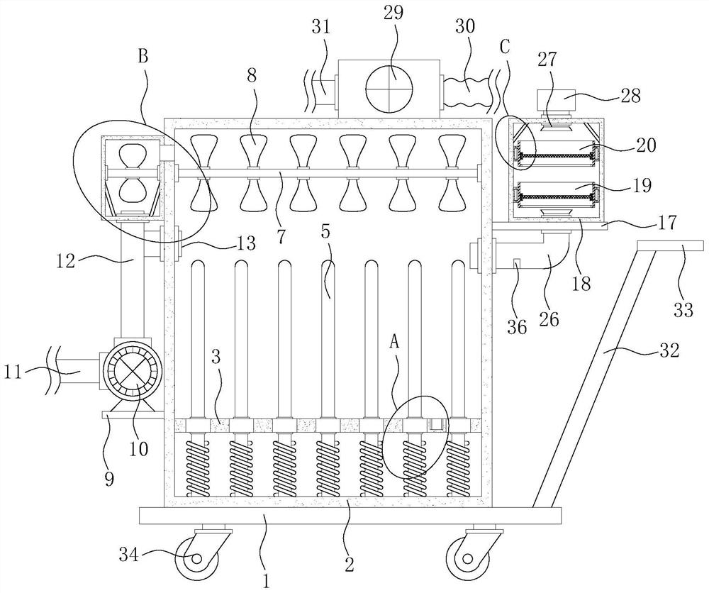
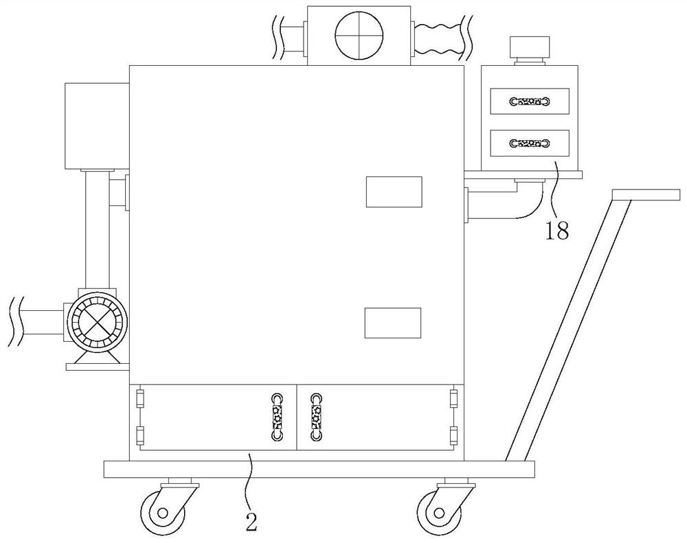
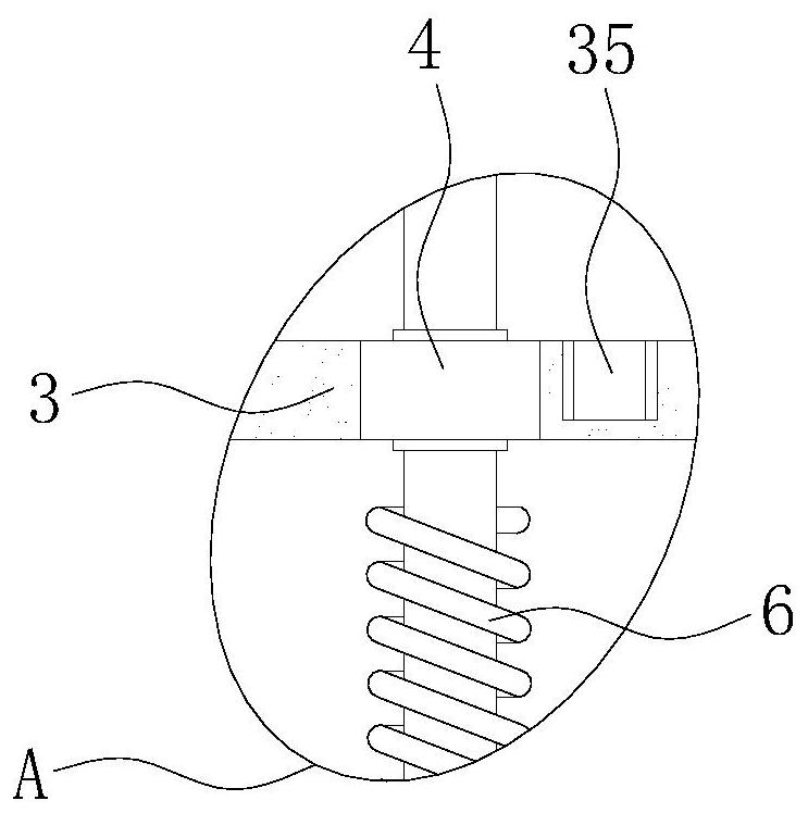
[0026] see Figure 1-5, the present invention provides a technical solution: an electromagnetic superconducting drying furnace, including a mounting plate 1, a drying furnace 2 is welded on the top outer surface of the mounting plate 1, and a partition plate is welded and installed inside the drying furnace 2 3. The partition plate 3 divides the drying furnace 2 into an upper cavity and a lower cavity. There is an opening on the partition plate 3, a sealing bl...


PUM


Abstract

The invention discloses an electromagnetic superconducting drying oven, and relates to the technical field of drying ovens. The electromagnetic superconducting drying oven comprises an installation plate, a drying oven body is welded to the outer surface of the top of the installation plate, a partition plate is welded to the interior of the drying oven body and divides the drying oven body into an upper cavity and a lower cavity, an opening is formed in the partition plate, a sealing block is fixedly installed in the opening, and a vacuum superconducting pipe is fixedly installed at the bottom of the drying oven body. On one hand, hot air generated by the vacuum superconducting pipe can be conveyed to needed materials, on the other hand, adsorption force during air suction can serve as apower source, and air in the vacuum superconducting pipe can be stirred conveniently, so that the liquidity of the hot air in the drying oven is effectively guaranteed, the situation that part of local heat of the vacuum superconducting pipe cannot be fully adsorbed and utilized due to direct adsorption is avoided, and the energy-saving efficiency of the drying oven is further guaranteed, and in addition, the cost of the mechanism is low, and the heat effect utilization rate can be fully increased again.

Description

technical field [0001] The invention relates to the technical field of drying furnaces, in particular to an electromagnetic superconducting drying furnace. Background technique [0002] The application of the drying furnace is quite extensive, and the utilization rate is also very high. The drying furnace burns a large amount of fuel to generate high temperature, and heats the air flowing through to generate high-temperature air to dry the product, which is not conducive to environmental protection and effective utilization of resources. . [0003] The authorized announcement number is CN209655771U patent, which discloses a new type of electromagnetic auxiliary heating system for drying room, which involves the technical field of drying room equipment, including drying workshop, drying furnace body and drying workshop. The drying workshop is fixed It is arranged inside the drying workshop, the drying furnace body is fixedly arranged inside the drying workshop, and a drying ...

Claims


Application Information

Patent Timeline
Patent Type & Authority Applications(China)
IPC IPC(8): F26B21/00F26B21/06F26B21/10F24H3/06
CPCF24H3/062F26B21/002F26B21/003F26B21/004F26B21/06F26B21/10
Inventor 魏春泉鄢增国
Owner 山东锦恒环保设备有限公司
Why Eureka
Try Eureka