
Distributed optical fiber sensing system utilizing filtering characteristics of Mach-Zehnder interferometer

A technology of distributed optical fiber and filtering characteristics, which is applied in the direction of transmitting sensing components, converting sensor output, and instruments by using optical devices, and can solve the positioning function that requires complex signal demodulation algorithms, cannot be accurately positioned, and the system is susceptible to environmental influences, etc. question

Pending Publication Date: 2021-03-19
SHANGHAI UNIV
View PDF8 Cites 1 Cited by
  • Summary
  • Abstract
  • Description
  • Claims
  • Application Information

AI Technical Summary

Problems solved by technology

Although the distributed optical fiber sensing system based on the interferometer structure has extremely high detection sensitivity to external disturbances, the Fabry-Perot interferometric system cannot realize fully distributed detection due to its structural limitations, and the reflection in the Michelson interferometric system The device will cause noise, which makes the phase susceptible to be affected, causing the problem of precise positioning, while the Sagnac interferometric system is susceptible to environmental noise, and the positioning function requires complex signal demodulation algorithms
The Mach-Zehnder interferometric system does not require demodulation, and the positioning method is simple. However, due to the use of a double-arm structure, the system is susceptible to environmental influences, and one of the interfering arms needs to be isolated for protection.

Method used


Image

  • Distributed optical fiber sensing system utilizing filtering characteristics of Mach-Zehnder interferometer
  • Distributed optical fiber sensing system utilizing filtering characteristics of Mach-Zehnder interferometer
  • Distributed optical fiber sensing system utilizing filtering characteristics of Mach-Zehnder interferometer

Examples


Embodiment 1

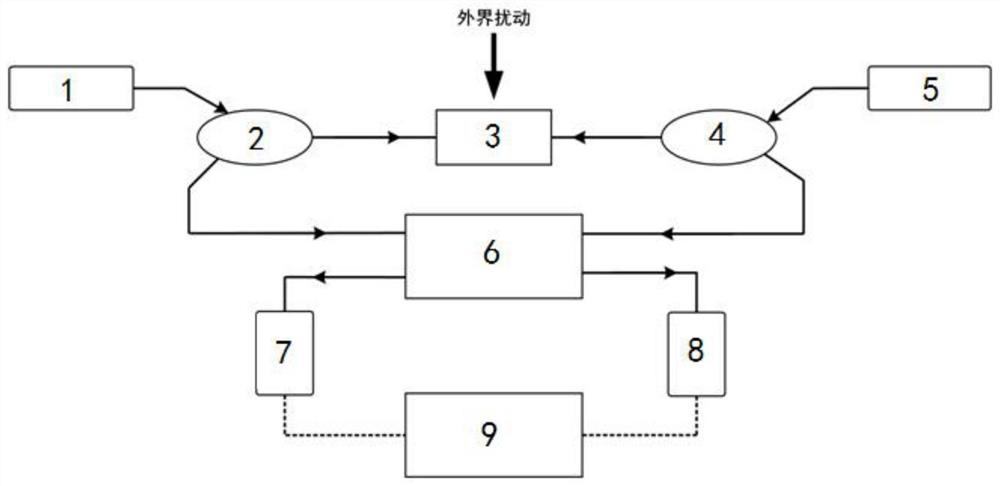
[0022] In this example, see figure 1 , a distributed optical fiber sensing system utilizing the filtering characteristics of a Mach-Zehnder interferometer, comprising sequentially connected laser A 1, coupler A 2, sensing fiber 3, coupler B 4, and laser B 5, characterized in that: The outputs of the coupler A 2 and the coupler B 4 are input into a Mach-Zehnder interferometer 6 from two opposite directions, and the two outputs of the Mach-Zehnder interferometer 6 pass through a photodetector A 7 and a photoelectric detector respectively. Detector B 8 converts the optical signal into an electrical signal and enters a data acquisition and processing unit 9; through the filtering characteristics of the Mach-Zehnder interferometer 6, the phase modulation of the light in the sensing fiber is converted into intensity modulation; The data collection and processing unit 9 is used to collect and process the two signal waveforms output by the two photodetectors A and B 7 and 8 to determi...

Embodiment 2

[0025] This embodiment is basically the same as Embodiment 1, especially in that:

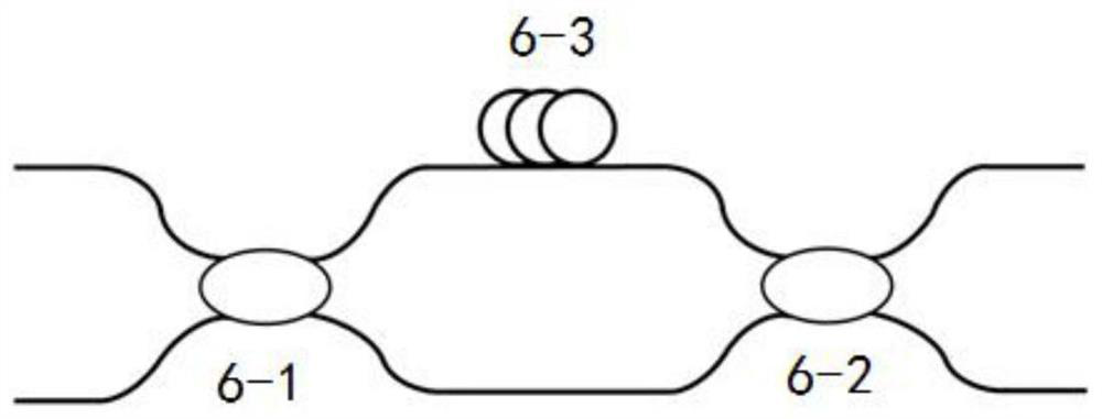
[0026] In this example, see Figure 1-Figure 2 , the Mach-Zehnder interferometer 6 is made up of two 2×2 couplers A and B 6-1, 6-2 and a delay fiber 6-3, and the two 2×2 couplers A and B 6-1, The coupling ratio of 6-2 is 50:50. The function of the delay fiber 6-3 is to construct an asymmetric Mach-Zehnder interferometer, and adjust its length to adjust the arm length difference and filter characteristics of the interferometer.

[0027] In this embodiment, the laser A 1 and the laser B 5 are both narrow-band lasers with good coherence, and the central wavelengths of the two may be different, but both are in the linear region of the filter characteristic of the Mach-Zehnder interferometer 6 .

[0028] In this embodiment, the output light of the laser A 1 or the laser B 5 is divided into two beams through another coupler, and input into the coupler A 2 and the coupler B 4 respectively, so as to s...

Embodiment 3

[0031] This embodiment is basically the same as the above-mentioned embodiment, and the special features are:

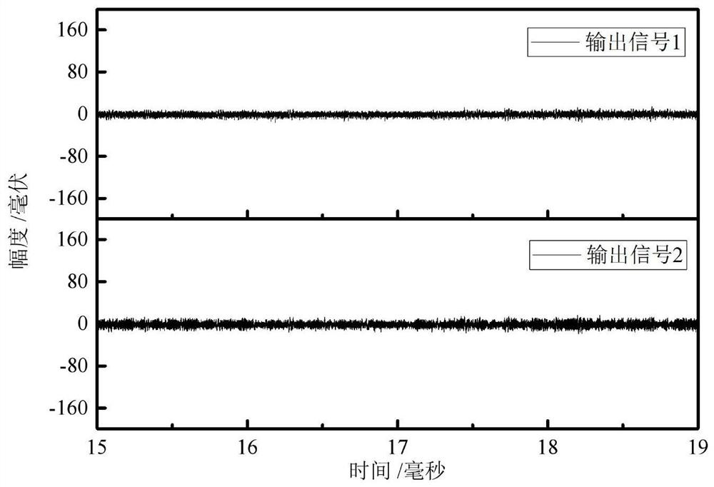
[0032] In this embodiment, a channel of Santec's multi-channel tunable laser ECL-200 is selected as laser A 1, and the output of laser A 1 is divided into two beams through a coupler with a coupling ratio of 50:50, and input Coupler A 2 and Coupler B 4. The output power of laser A 1 is 3mW, and the center wavelength is 1529.44nm. Photodetectors A and B 7 and 8 are 10Gbps photodetector modules with preamplification from Beijing Minguang Technology Co., Ltd. All optical fibers are G.652 standard single-mode optical fibers, wherein the lengths of the sensing optical fiber 3 and the delay optical fiber 6-3 are 2.7624km and 1km, respectively. The coupling ratio of the two 2×2 couplers A and B 6-1 and 6-2 is 50:50. The data acquisition and processing system 9 consists of a DELL Inspiron 5548 laptop computer and a PicoScope 5203 digital oscilloscope from the British PICO...


PUM


Abstract

The invention discloses a distributed optical fiber sensing system utilizing filtering characteristics of a Mach-Zehnder interferometer. The system comprises a first laser device, a first coupler, a sensing optical fiber, a second coupler and a second laser device. Output light of the first coupler and output light of the second coupler are inputted into the Mach-Zehnder interferometer from two opposite directions. Two outputs of the Mach-Zehnder interferometer are respectively converted into electric signals through a first photoelectric detector and a second photoelectric detector, and the electric signals enter the data acquisition and processing unit. The Mach-Zehnder interferometer is composed of two 2 x 2 couplers and a delay optical fiber. Through the filtering characteristic of theMach-Zehnder interferometer, phase modulation of light in the sensing optical fiber is converted into intensity modulation. The data acquisition and processing unit is used for acquiring and processing two paths of signals outputted by the system and determining whether disturbance occurs or not and the position of the disturbance. The system is simple in structure, adjustable in sensitivity andgood in stability.

Description

technical field [0001] The invention relates to a distributed optical fiber sensing system, in particular to a distributed optical fiber sensing system utilizing the filtering characteristics of a Mach-Zehnder interferometer, belonging to the field of optical fiber sensing. Background technique [0002] With the rapid development of the national economy and the large-scale construction of global infrastructure, the demand for quality monitoring of large buildings and industrial equipment and perimeter security alerts is increasing day by day. The distributed optical fiber sensing system uses optical fiber as the sensing unit and transmission medium, which can realize the monitoring of external vibration signals under continuous long-distance conditions. It has the advantages of simple structure, wide frequency band response, wide measurement range, and high precision, and can work for a long time In environments with harsh conditions such as high temperature and high humidit...

Claims


Application Information

Patent Timeline
IPC IPC(8): G01D5/353
CPCG01D5/35329
Inventor 方捻孟祥林王陆唐王春华
Owner SHANGHAI UNIV
Learn More