
Plastic laser transmittance detection equipment

A technology of laser transmission and laser transmitter, applied in transmittance measurement and other directions, to achieve the effect of improving portability and stability, accurate and stable laser transmittance, and reducing defective rate

Pending Publication Date: 2021-03-19
WENZHOU INST OF TECH TESTING & CALIBRATION
View PDF8 Cites 0 Cited by
  • Summary
  • Abstract
  • Description
  • Claims
  • Application Information

AI Technical Summary

Problems solved by technology

[0006] The purpose of the present invention is to solve the shortcomings in the prior art that there is no complete solution that can conveniently and effectively realize the detection of plastic transmittance, and propose a plastic laser transmittance detection equipment

Method used


Image

  • Plastic laser transmittance detection equipment
  • Plastic laser transmittance detection equipment
  • Plastic laser transmittance detection equipment

Examples


Embodiment 1

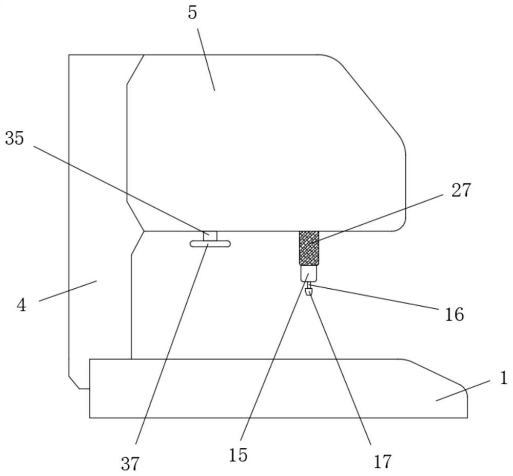
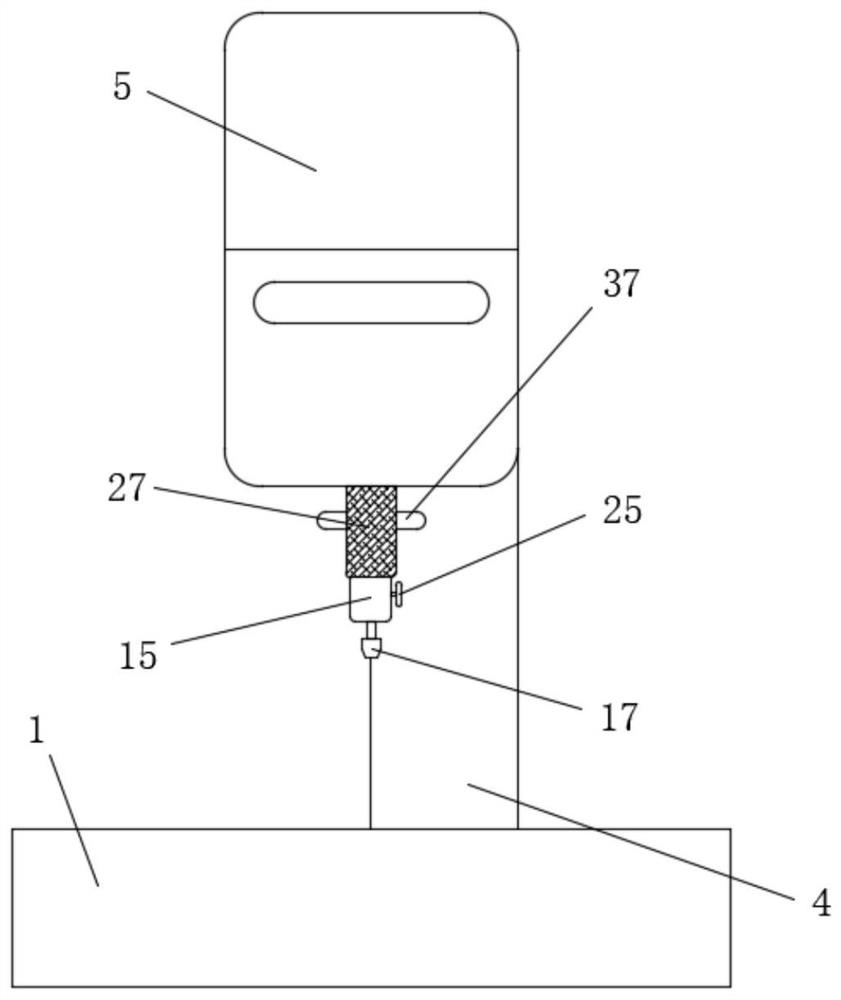
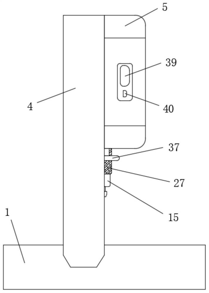
[0043] refer to Figure 1-11 , a plastic laser transmittance detection equipment, including a hardware system 100 and a software system 200, and a test platform 1 and a support column 4 for installing the hardware system 100, and the support column 4 is fixedly connected to the top side of the test platform 1, The top of the measuring platform 1 is provided with a sample placement slot 2, and the hardware system 100 includes a CPU module 1001, a power supply module 1002, a laser output module 1003, a power detection module 1004, a handheld module 1005, a data output module 1006, and a man-machine interface 1007, software The system 200 includes a real-time operating system 2001, a calibration system 2002, a data acquisition program 2003, a signal display program 2004, a data reading and writing program 2005, and a communication system 2006. The CPU module 1001 uses an imported semiconductor single-chip microcomputer, and the power supply module 1002 is the entire circuit Provi...

Embodiment 2

[0045] Further improvement on the basis of the first embodiment: the bottoms of the four support plates 9 are provided with chute 10, and the four chute 10 are slidingly connected with sliders 11, and the bottoms of the four sliders 11 respectively extend to the corresponding The bottom of the support plate 9 is connected with connecting rods 12 in rotation, and the ends of the four connecting rods 12 extending close to each other are respectively connected to the top of the movable plate 13 in equidistant rotation, through the cooperation of the slider 11 and the connecting rods 12, it is easy to move. Any movement of the plate 13 in the horizontal position, two rollers 38 are symmetrically rotated on both sides of the four sliders 11, and a plurality of rollers 38 are respectively connected to the inner wall of the chute 10 by rolling, and the rollers 38 are used to facilitate the movement of the sliders 11. The sliding of the movable plate 13 improves the flexibility of move...


PUM


Abstract

The invention belongs to the technical field of optical-mechanical-electrical integration, particularly relates to plastic laser transmissivity detection equipment, and provides the following scheme aiming at a problem that no complete solution can conveniently and effectively realize plastic transmissivity detection in the prior art. The device comprises a hardware system, a software system, a test bench used for installing the hardware system and a support column, wherein the support column is fixedly connected to one side of the top of the test bench, and a sample placing groove is formed in the top of the test bench; accuracy and stability of laser transmissivity are ensured through multiple measures such as a laser, a high-precision power supply and a transmissivity calibration sheetwhich output stably, a special-shaped sample can be tested by developing a handheld measuring head, the adaptive capacity is enhanced, meanwhile, portability and stability are improved, and the probecan be accurately and stably measured by integrating SPS into a special laser welding automation system; and the laser output power is adjusted in real time, and the defective rate can be greatly reduced.

Description

technical field [0001] The invention relates to the technical field of optical-mechanical-electrical integration, in particular to equipment for detecting plastic laser transmittance. Background technique [0002] Most of the plastic products are molded products. Due to the limitations of injection molding, extrusion and other processes, a considerable part of the products cannot be processed and formed at one time due to the limitations of size, shape and structure, and require secondary processing for connection. Therefore, the connection process has become the manufacturing of plastic materials. Key steps of the assembly. As the demand for composite components, especially structural components, increases, so does the use of joining processes. [0003] The traditional connection method of thermoplastics has many disadvantages: mechanical connection strength such as screws and snap rings is easy to meet the requirements, but the quality of the connection surface cannot be ...

Claims


Application Information

Patent Timeline
Patent Type & Authority Applications(China)
IPC IPC(8): G01N21/59
CPCG01N21/59
Inventor 吴杰黄山石方温至陈继宣杨立委郑晓周
Owner WENZHOU INST OF TECH TESTING & CALIBRATION
Learn More