

Five-axis numerical control machine tool rotating shaft structure parameter error compensation method
A technology of CNC machine tools and structural parameters, applied in the field of CNC machine tools, can solve the problems of cumbersome detection process, unsatisfactory precision, multiple disassembly and assembly, etc., and achieve the effect of simple detection process
- Summary
- Abstract
- Description
- Claims
- Application Information
AI Technical Summary
Problems solved by technology
Method used
Image

Examples
Embodiment 1
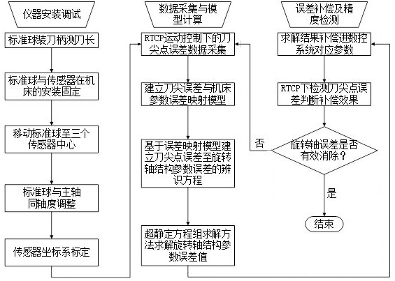
[0050] A method for compensating the structural parameter error of the rotary axis of a five-axis CNC machine tool, such as figure 1 , including the following steps:
[0051] Step S1: When the RTCP function of the five-axis CNC machine tool is turned on, according to the preset detection trajectory, the rotation stroke of each rotation axis of the five-axis CNC machine tool is divided into multiple nodes, and the machine tool is controlled during the detection process of each rotation axis Swing to a given node;
[0052] Step S2: Collect and record the offsets of the tool center point at each node relative to the initial position in the three directions of X-axis, Y-axis, and Z-axis. The collected tool point error data sequences are recorded as ;
[0053] Step S3: Under the action of the offset error of the tool center point, establish a mathematical model for identifying the structural parameter error of the rotary axis based on the position deviation of the tool tip point...
Embodiment 2
[0059] This embodiment is on the basis of embodiment 1, as figure 1 , the method for calculating the structural parameter error of the rotary axis of the machine tool in the step S3 is specifically:
[0060] Step S301: According to the structural parameters of the current rotating axis in the numerical control system of the five-axis numerical control machine tool, establish the theoretical position of the tool tip point under a certain node of the rotational axis of the five-axis numerical control machine tool The mathematical model of is:
[0061]
[0062] Among them, θ is the angle of the rotation axis at the sampling point; a, b, and c are the direction vectors of the rotation axis saved in the CNC system The three elements of are unit vectors; s, l, h are the position parameter components in the three directions of the rotation center in the machine space coordinate system saved in the CNC system; these parameters can be obtained through the CNC system and are known...
Embodiment 3
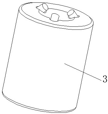
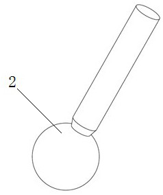
[0083] Present embodiment is on the basis of embodiment 1 or 2, as Figure 2-Figure 5 , before the step S1, the standard ball head 2 is installed on the five-axis CNC machine tool through the tool handle 1, and the standard ball head 2 is installed on the five-axis CNC machine tool by moving the linear coordinate axis of the machine tool when each rotation axis of the five-axis CNC machine tool is in the initial state. Move to the origin position of the non-contact three-way displacement sensor 3, adjust the ball center of the standard ball head to the spindle axis of the five-axis CNC machine tool through the adjustment structure on the tool handle 1, to ensure the non-contact during the slow rotation of the spindle The data variation of the three-way displacement sensor 3 is within ±0.001mm.
[0084] Other parts of this embodiment are the same as those of Embodiment 1 or 2 above, so details are not repeated here.
PUM
 Abstract
Description
Claims
Application Information