Processing method and processing device of preservative-free seedless preserved plums
A processing device and processing method technology, applied in the fields of application, food processing, food science, etc., can solve problems such as difficult salvage, broken cores are easy to be swallowed, and achieve the effects of easy salvage, time saving, and manpower saving
- Summary
- Abstract
- Description
- Claims
- Application Information
AI Technical Summary
Problems solved by technology
Method used
Image

Examples
Embodiment 1
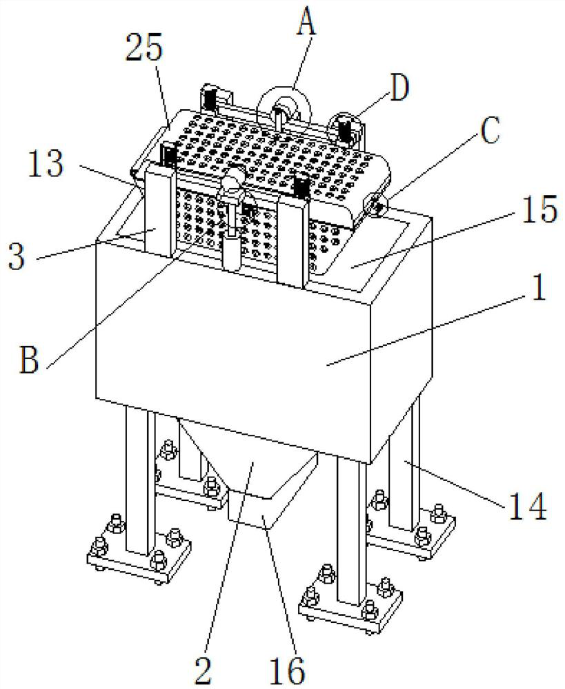
[0041] Embodiment 1 has introduced a kind of processing method and processing device of seedless plum cake without adding preservatives, wherein by opening a water tank 15 on the base 1, the sieve frame 13 can be washed inside the water tank 15, and through the pulp and The impact of water completely removes the broken core connected with the pulp; by fixedly connecting the broken core collection bucket 2 at the bottom of the water tank 15, the nature of the large specific gravity of the broken core itself can be used to realize natural precipitation in the broken core collection bucket 2 , and finally processed through the outlet. details as follows:
[0042] A kind of processing method and processing device of seedless plum cake without adding antiseptic, such as figure 1 As shown, the processing device includes a base 1 and a broken nuclear collection bucket 2; the four corners of the lower surface of the base 1 are respectively fixedly connected with a supporting leg 14, ...
Embodiment 2
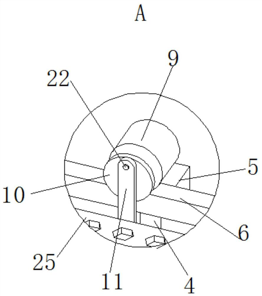
[0045] Embodiment 2 is an improvement on the basis of Embodiment 1. The main improvement is that the pulp can be fixed within a certain range for cleaning by setting the screen frame 13 with the screen frame cover 25, which is convenient for the salvage of the pulp and saves time; The addition of support columns 3, support cross bars 6 and electric telescopic rods 4 can realize the automatic lifting and lowering of the screen frame 13, which is convenient for loading or unloading materials to the inside of the screen frame 13 and saves manpower; one end of the screen frame 13 and the screen frame cover 25 Rotational connection, fixed connection at one end, convenient for storage of screen frame cover 25 during loading and unloading operations; by setting spring 1 7 and spring 2 8 on fixed column 22, it can buffer the rise and fall of screen frame 13 The function can not only ensure uniform flushing, but also avoid direct collision between the fixed sleeve 19, the screen frame 1...
Embodiment 3
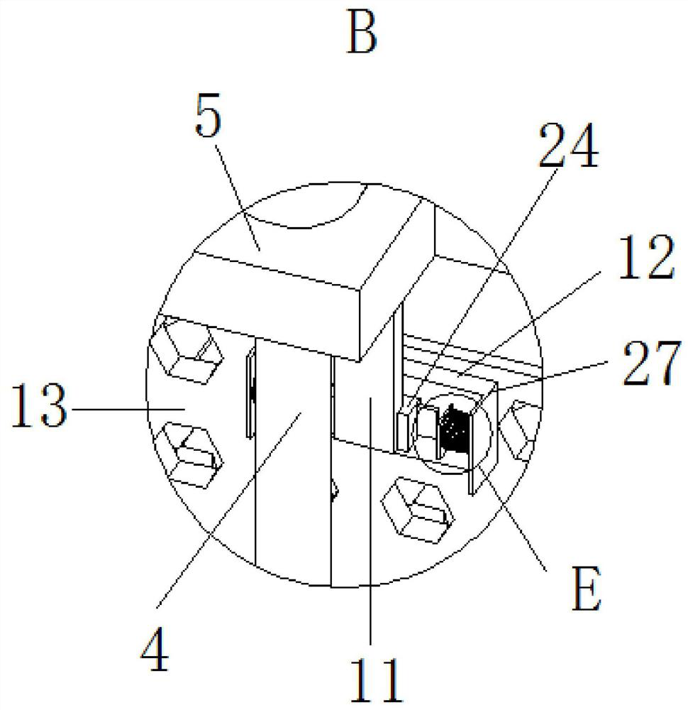
[0052] Embodiment 3 is an improvement on the basis of Embodiment 2. The main improvement is that by adding balls 35 inside the T-shaped chute 17, the friction between the T-shaped slider 18 and the T-shaped chute 17 can be reduced. The screw rod 34 is threaded on the plate 21. When the device is not working, the screw rod 34 is rotated to the bottom of the screw rod 34 to contact the upper surface of the fixed sleeve 19, and the entire screen frame 13 and the screen frame cover can be supported by the screw rod 34 and the fixed sleeve 19. 25 and other parts, the spring one 7 is released from the compressed state, which is beneficial to prolong the service life of the spring one 7, and the clamping block 32 is fixedly connected inside the fixed sleeve 19, and a clamping groove 33 is provided on the connecting column 20 to avoid connection The radial rotation of the column 20 and the fixed sleeve 19 ensures that the reciprocating movement of the connecting column 20 along the fix...
PUM
 Abstract
Description
Claims
Application Information
PatSnap Eureka turns technology decisions into work you can execute. Powered by our Innovation Knowledge Graph, it runs expert workflows across engineering, life sciences, materials and intellectual property. Get your review-ready output in minutes.


