Metal powder continuous extrusion forming device

A technology of extrusion molding and metal powder, which is applied in the direction of metal processing, etc., can solve the problems of low production efficiency, different density of extruded blocks, cumbersome procedures, etc.

Inactive Publication Date: 2021-03-23
沈超
View PDF7 Cites 1 Cited by
  • Summary
  • Abstract
  • Description
  • Claims
  • Application Information

AI Technical Summary

Problems solved by technology

[0004] However, manual discharge is often used in the discharge process of metal powder extrusion processing in the past, and manual cutting is also mostly used in the cutting process of procedures. Therefore, it is necessary to stop the operation of the machine during the discharge process to perform manual discharge work. The process is cumbersome and the extrusion efficiency is low, and the density of the extruded blocks is not the same. In addition, during the cutting process, the extruded blocks need to be placed, then the machine is turned on for cutting, and finally the collection operation is required. The process is time-consuming and labor-intensive, and the production efficiency is low. In order to solve the above problems, a metal powder continuous extrusion molding device is proposed

Method used


Image

  • Metal powder continuous extrusion forming device
  • Metal powder continuous extrusion forming device
  • Metal powder continuous extrusion forming device

Examples


Embodiment Construction

[0027] Next, the technical solutions in the embodiments of the present invention will be apparent from the embodiment of the present invention, and it is clearly described, and it is understood that the described embodiments are merely embodiments of the present invention, not all of the embodiments.

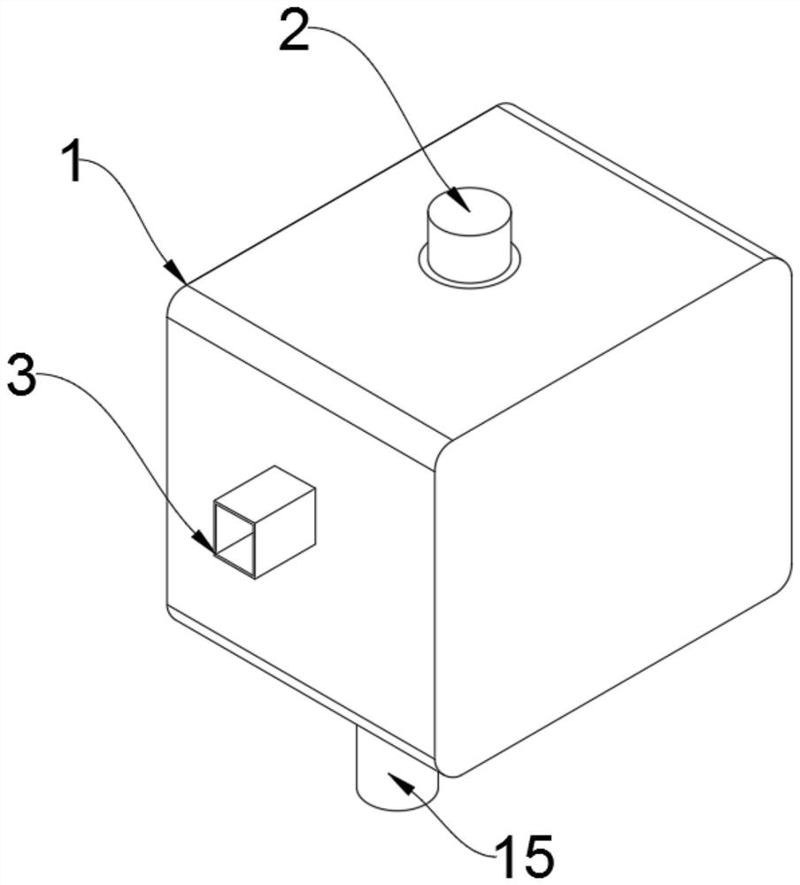
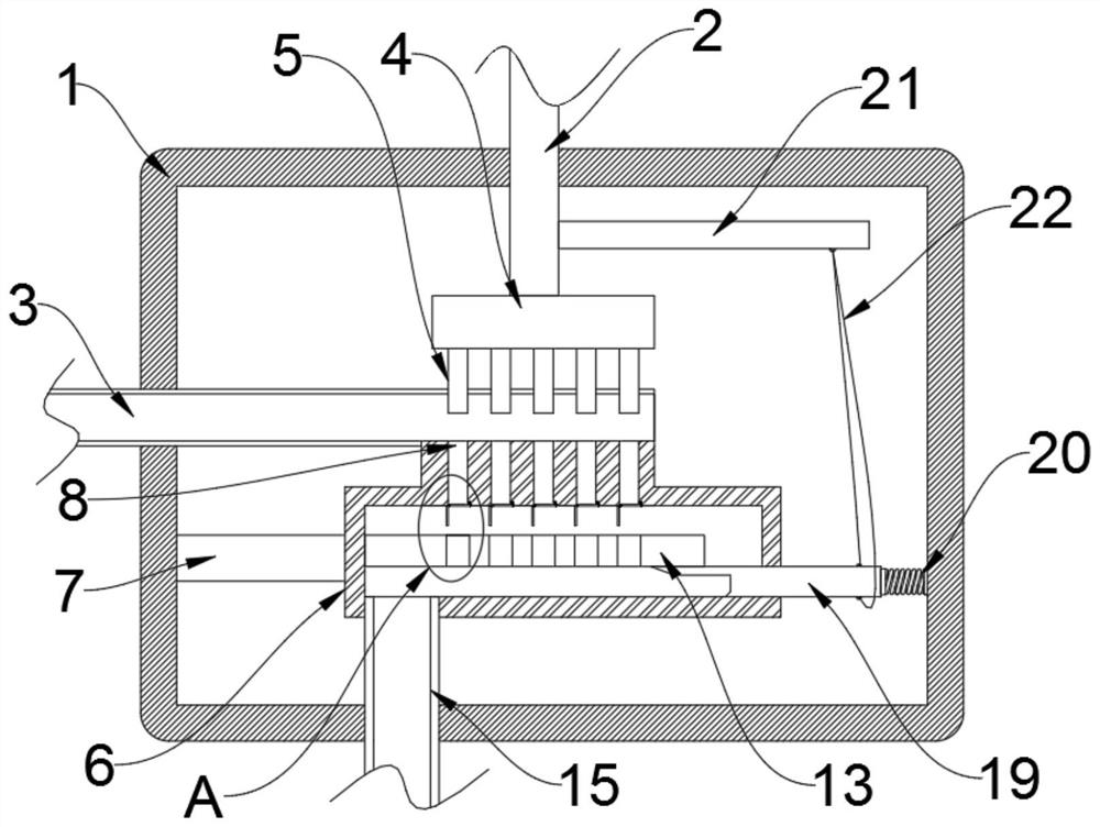
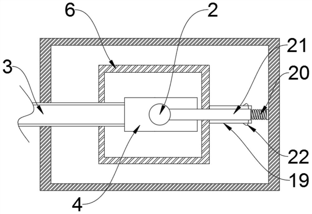
[0028] Refer Figure 1-7, A metal powder continuously extruded molding device, including the box 1, the pressure rod 2, and the left side wall of the casing 1, the feed tube port is fixedly mounted, and the rod 2 is slidably connected to the upper side wall of the casing 1, the pressure rod 2 The lower wall fixing is attached to the extruded disc 4, and the lower side wall of the extrudation disk 4 is fixedly connected to the plurality of extruded rods 5, the pressing rod 5 and the feed tube port slit, the feed tube 3 The lower end is fixedly connected to the extrusion collection box 6, and the extrusion collecting box 6 and the left side wall of the casing 1 are connected by the sup...


PUM


Abstract

The invention discloses a metal powder continuous extrusion forming device. The metal powder continuous extrusion forming device comprises a box body and a pressing rod, a feeding pipe opening is fixedly formed in the left side wall of the box body, the pressing rod is slidably connected to the upper side wall of the box body, an extrusion disc is fixedly connected to the lower side wall of the pressing rod, a plurality of extrusion rods are fixedly connected to the lower side wall of the extrusion disc, the extrusion rods are slidably connected with the side wall of the upper end of the feeding pipe opening, the lower end of the feeding pipe opening is fixedly connected with an extrusion collecting box, the extrusion collecting box is connected with the left side wall of the box body through a supporting rod, a plurality of extrusion notches are formed in the upper side wall of the extrusion collecting box, and a rotary plate cavity is formed in the right side wall of the extrusion notches. Through the cooperation of the extrusion rods, a cutting mechanism, a blocking mechanism, a rotary baffle, springs and traction ropes, equal-density extrusion and automatic discharging operation on metal powder are achieved, and meanwhile the equal-length cutting and pushing effects on the metal powder after the metal powder is blocked are achieved through the driving effect.

Description

Technical field [0001] The present invention relates to the field of metal extrusion, and more particularly to a metal powder continuous extrusion molding device. Background technique [0002] With the development of economic globalization, the development of heavy industry has become an indispensable part of a country. Industrial production can be referred to as industrial manufacturing. In China, industrial manufacturing is to create resources, according to the main needs of the market, by manufacturing process In order to carry out the transformation of industrial products and commercial buildings that can be used. At present, as the pillar industry of China's national economy, heavy industry is one of the leading departments of China's economic growth, as an important economic and social development. To rely, in addition, the heavy industry is the main channel of China's urban employment and the specific embodiment of international competitiveness. Among them, the metal mater...

Claims


Application Information

Patent Timeline
Patent Type & Authority Applications(China)
IPC IPC(8): B22F3/20B22F3/00B22F3/24B23D79/00B23Q7/06
CPCB22F3/003B22F3/005B22F3/20B22F3/24B23D79/00B23Q7/06
Inventor 沈超
Owner 沈超
Why Eureka
Try Eureka