Automatic arch frame lifting device for cantilever type heading machine and working method thereof

A cantilever-type roadheader and automatic lifting technology, which is applied in shaft equipment, earthwork drilling, wellbore lining, etc., can solve the problems of increasing mechanical loss and energy consumption, taking up construction time, and reducing construction economic benefits

Pending Publication Date: 2021-03-23
CITIC HEAVY INDUSTRIES CO LTD +1
View PDF0 Cites 0 Cited by
  • Summary
  • Abstract
  • Description
  • Claims
  • Application Information

AI Technical Summary

Problems solved by technology

The repeated entry and exit of this kind of machinery virtually increases the loss and energy consumption of the machinery, increases the maintenance cost of the machinery, and reduces the economic benefits of construction; The ineffective working time of leaving the site is also continuously increasing, especially in the excavation construction of ultra-long tunnels. This invalid working time of entering and leaving the site accounts for most of the construction time and has a huge impact on the construction speed of the roadheader.

Method used


Image

  • Automatic arch frame lifting device for cantilever type heading machine and working method thereof
  • Automatic arch frame lifting device for cantilever type heading machine and working method thereof
  • Automatic arch frame lifting device for cantilever type heading machine and working method thereof

Examples


Embodiment Construction

[0021] The technical solution of the present invention will be described in further detail below in conjunction with the accompanying drawings and embodiments.

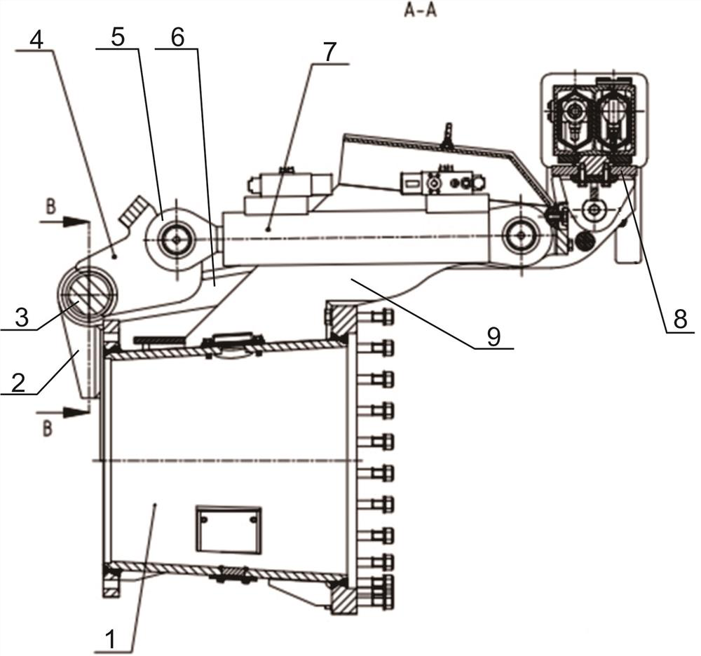
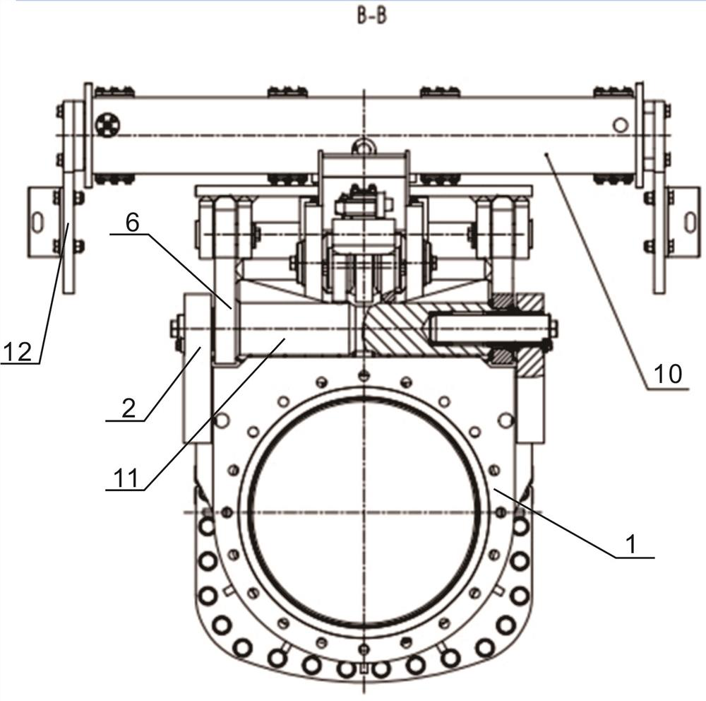
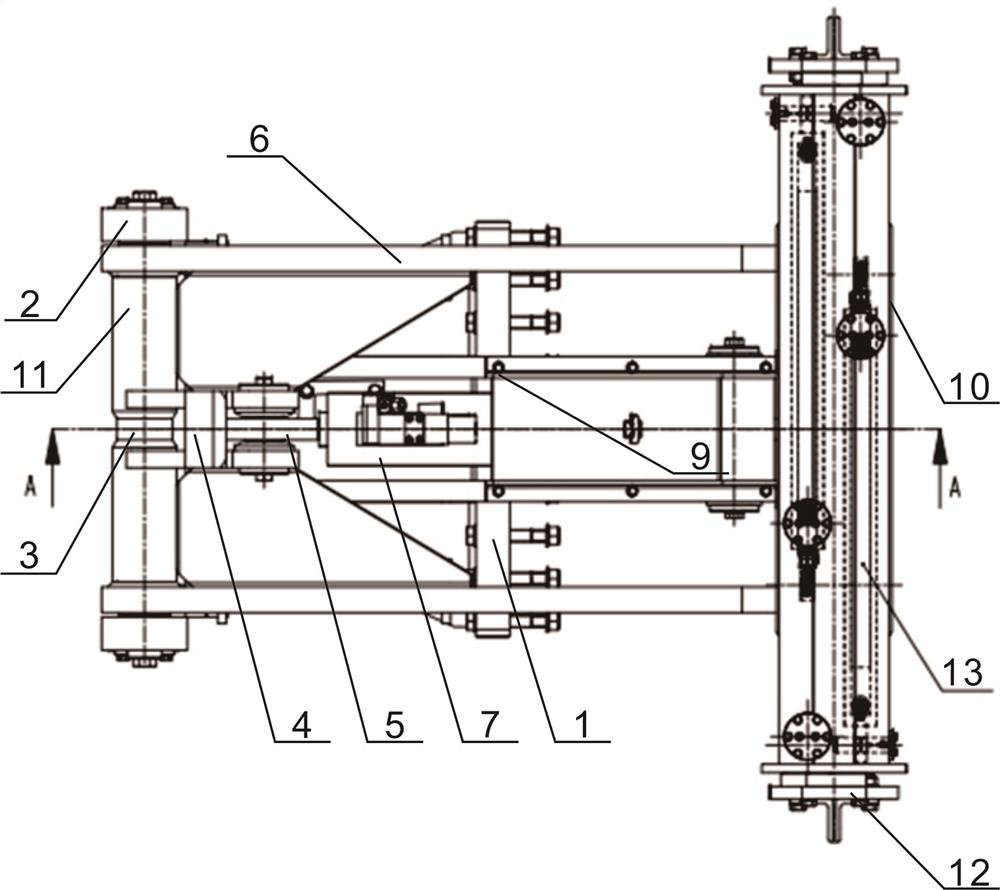
[0022] Such as Figure 1~6 As shown, the automatic arch lifting device for the cantilever roadheader includes a frame 1, a lifting arm 6, an adjustment cylinder 7 and a rotating platform 8. The frame 1 is installed on the cutting arm of the cantilever roadheader, and one end of the top of the frame is Mounting plates 2 located at the front and rear sides of the frame are installed, and a positioning shaft 3 located above the frame is fixedly installed between the two mounting plates. Two shaft sleeves 11 are set on the positioning shaft, and there is a gap between the inner end surfaces of the two shaft sleeves. The adjustment oil cylinder 7 is fixedly installed in the center of the top of the frame 1 through the mounting seat 9, the piston rod of the adjustment oil cylinder faces the two axle sleeves, and the earring...


PUM


Abstract

The invention discloses an automatic arch frame lifting device for a cantilever type heading machine. The automatic arch frame lifting device comprises a frame, lifting arms, an adjusting oil cylinderand a rotating platform, wherein the frame is mounted on a cutting arm of the cantilever type heading machine; a positioning shaft positioned above the frame is fixedly mounted at one end of the topof the frame; two shaft sleeves are mounted on the positioning shaft in a sleeving manner; the adjusting oil cylinder is fixedly mounted in the center of the top of the frame; a piston rod of the adjusting oil cylinder is hinged to the two shaft sleeves; the two lifting arms are respectively positioned on two sides of the adjusting oil cylinder; one end of each of the two lifting arms is and fixedly mounted on the corresponding shaft sleeve in a sleeving manner; the rotating platform is fixedly mounted at the other ends of the lifting arms; a balance rod is fixedly mounted at the top of the rotating platform; two telescopic oil cylinders are mounted inside the balance rod; piston rods of the two telescopic oil cylinders respectively extend out of two ends of the balance rod; and positioning plates are mounted at the end parts of the piston rods. The invention further discloses a working method of the automatic arch frame lifting device. According to the automatic arch frame lifting device disclosed by the invention, the mechanization and automation degree of arch frame mounting can be improved, and conditions are provided for integrated construction of 'anchor digging and spraying'of the cantilever type heading machine.

Description

technical field [0001] The invention belongs to the technical field of tunnel excavation and construction, and relates to construction equipment for arch support in tunnels, in particular to an automatic arch lifting device for a cantilever type boring machine and a working method thereof. Background technique [0002] At present, in the construction of tunnels with weak surrounding rocks in China, it is necessary to install arches and cooperate with reinforced mesh shotcrete support to strengthen the structural strength of tunnel surrounding rocks. The lifting and installation of the arch frame is divided into manual and mechanical methods: 1. The manual installation method is to lift the arch frame on the edge of the rock formation by manpower, fix it with anchor rods, and then connect it into a ring in turn to form the surrounding rock. supporting structure. The single-piece weight of the arch frame is generally more than 100Kg, which requires the cooperation of multiple...

Claims


Application Information

Patent Timeline
Patent Type & Authority Applications(China)
IPC IPC(8): E21D11/18E21D11/40E21D9/10
CPCE21D9/1093E21D11/18E21D11/183E21D11/40
Inventor 崔郎郎黎飞胡国辉王巍峰李政曹立钢苗军克郭守乾张晓明童诏孟永红陈明牛婷志史永胜
Owner CITIC HEAVY INDUSTRIES CO LTD
Why Eureka
Try Eureka