Supercharge Your Innovation With Domain-Expert AI Agents!

Power source control device

A technology of control device and power source, applied in the field of power source, can solve the problem of no retrieval, etc., and achieve the effect of reducing the loss in the system

Active Publication Date: 2021-03-23
STATE GRID SICHUAN ELECTRIC POWER CORP ELECTRIC POWER RES INST
View PDF12 Cites 2 Cited by
  • Summary
  • Abstract
  • Description
  • Claims
  • Application Information

AI Technical Summary

Problems solved by technology

[0003] In the existing technology, the design of frequency conversion often focuses on the outside, and how to intervene in the relationship between voltage, current and frequency from the source has not been retrieved in the prior art

Method used


Image

  • Power source control device
  • Power source control device
  • Power source control device

Examples


Embodiment 1

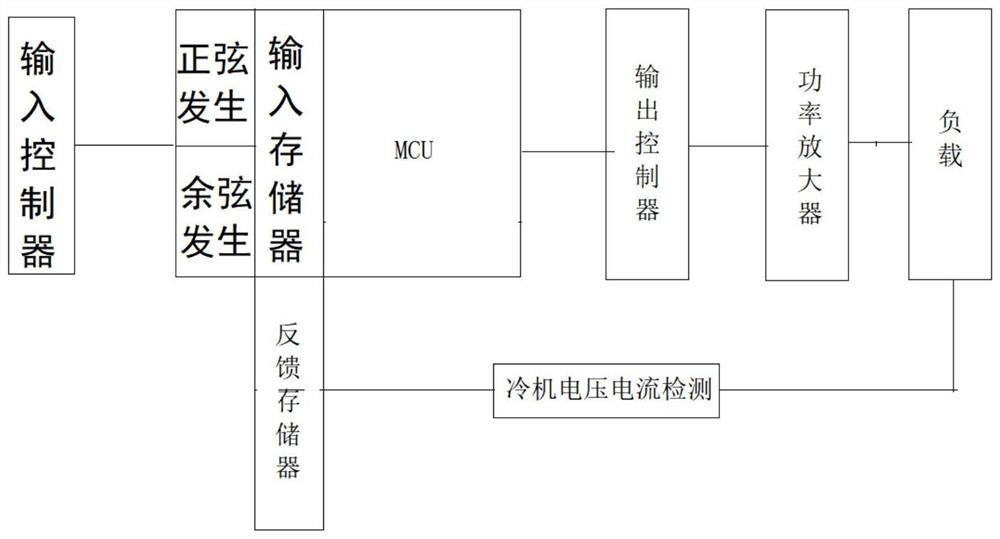
[0024] This embodiment provides a power source control device, such as figure 1 As shown, the whole is divided into four parts: input part (i.e. input controller), adjustment part (i.e. amplitude frequency modulation machine), output part (i.e. output controller) and load. The focus of this embodiment is on the adjustment part, especially Feedback circuit for the regulation section; specifically, as figure 1 , the power source consists of an input controller, an output controller, a power amplifier and a load. The input controller is a controller for setting a certain power value, which can be a remote controller or other input devices, and an input panel that can provide amplitude, frequency and phase input. This embodiment takes this as an example temporarily.

[0025] Sine and cosine are generated by setting the amplitude, frequency and phase in the input controller, and the output is controlled by the output controller; there is a sub-frequency regulator between the inpu...

Embodiment 2

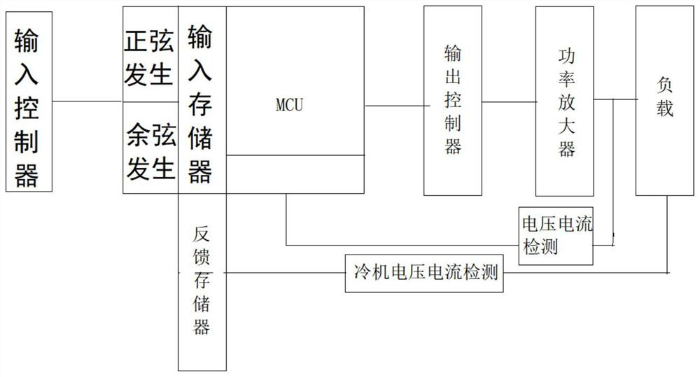
[0027] Further improvement on the basis of Embodiment 1, in order to prevent errors in data or errors in output control or power amplifiers, further correction is required, and a correction loop is set between the power amplifier and the load, and the correction loop is It consists of a current and voltage probe and an AD converter. A correction memory is added in the sub-frequency regulator. The input of the correction memory is connected to the output of the AD converter, and the output of the correction memory is connected to the MCU. The voltage power at the output terminal is detected by the current and voltage probe, and then returned to the sub-frequency regulator for further judgment and superposition. After multiple cycles, a stable electric wave flow is formed. The electric wave formed in this way is smoother, and for the load, the frequency conversion is not so severe; thus further protecting the load equipment.
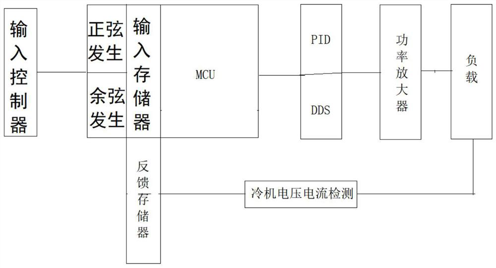
[0028] Example 2

[0029] Further improve on the ba...


PUM


Abstract

The invention discloses a power source control device, which comprises a sub-frequency regulator, wherein the sub-frequency regulator comprises a sine generator, a cosine generator, an MCU and an input memory, the output ends of the sine generator and the cosine generator are both connected with the input end of the input memory, the output end of the input memory is connected with the MCU, the input ends of the sine generator and the cosine generator are connected with the input end of an input controller, the output end of the MCU is connected with the input end of an output controller, theoutput end of the output controller is connected with the input end of a power amplifier, the output end of the power amplifier is connected with a load, the input end of a feedback memory is connected with the load, the output end of the feedback memory is connected with the second input pin of the MCU, and the feedback memory is used for caching and storing historical information. According to the invention, after power is set manually, the power is automatically converted into frequency sine and cosine values, the waveform of sine and cosine waves is automatically intervened through a chip,and then the sine and cosine waves are converted and output, so that the purpose of reducing external intervention to achieve positive power is achieved.

Description

technical field [0001] The present invention relates to the technical field of power sources, in particular to one. Background technique [0002] As the power supply of the frequency conversion speed regulation system, the frequency converter is widely used. How to accurately measure the loss and efficiency of the frequency converter and the loss and efficiency of the frequency conversion motor is a major issue to be solved urgently in the technology of frequency conversion speed regulation. Electrical reference values ​​mainly include voltage, current amplitude, frequency, phase angle of voltage and current, and power, etc., which mainly rely on various voltage, current, frequency, and power sensors and instruments for visual display. The power source is a standard metering device that generates standard voltage, current, frequency and power signals to calibrate voltage, current, frequency and power sensors and meters. Using its correction function, it is a new problem ra...

Claims


Application Information

Patent Timeline
Patent Type & Authority Applications(China)
IPC IPC(8): G01R1/28G05B19/042H03F3/20H02M1/00
CPCG01R1/28G05B19/0423H03F3/20H02M1/00G05B2219/21151Y02B70/10
Inventor 张扬帆邓舒予沈文琪肖丽刘芸刘柯里贾岩龙袁世炯何培东
Owner STATE GRID SICHUAN ELECTRIC POWER CORP ELECTRIC POWER RES INST
Features
  • R&D
  • Intellectual Property
  • Life Sciences
  • Materials
  • Tech Scout
  • Unparalleled Data Quality
  • Higher Quality Content
  • 60% Fewer Hallucinations
Learn More