
Permanent magnet outer rotor aerator

A technology for external rotors and aerators, applied to synchronous motors with stationary armatures and rotating magnets, electromechanical devices, and control of mechanical energy. It can solve the problems of large heat generation, inconvenient adjustment, inconvenient fixing and use, etc. , to achieve the effect of reducing installation work and improving disassembly efficiency

Active Publication Date: 2021-03-26
湖北梨威机械设备有限公司
View PDF8 Cites 2 Cited by
  • Summary
  • Abstract
  • Description
  • Claims
  • Application Information

AI Technical Summary

Problems solved by technology

The traditional asynchronous motor is inconvenient to adjust and generates a lot of heat, while the permanent magnet structure can realize stepless speed regulation
Generally, a stirring mechanism puts a stirring shaft underwater, and a motor is fixed above the water surface to drive the stirring shaft. For large-scale aquaculture, this kind of stirring mechanism is inconvenient to fix and use.

Method used


Image

  • Permanent magnet outer rotor aerator
  • Permanent magnet outer rotor aerator
  • Permanent magnet outer rotor aerator

Examples


Embodiment Construction

[0039] The principles and features of the present invention will be described below in conjunction with specific embodiments, and the examples given are only used to explain the present invention, and are not intended to limit the scope of the present invention. Unless defined otherwise, all technical and scientific terms used herein have the same meaning as commonly understood by one of ordinary skill in the technical field of the invention. The terms used herein in the description of the present invention are for the purpose of describing specific embodiments only, and are not intended to limit the present invention.

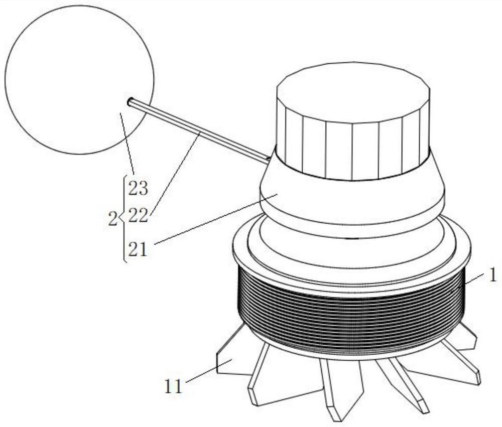
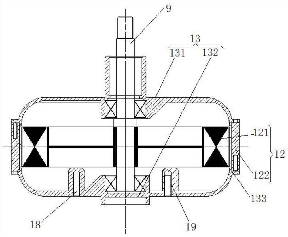
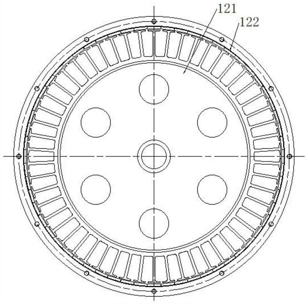
[0040] A permanent magnet outer rotor aerator, such as figure 1 As shown, it includes a stirring part 1 and a suspension part 2; the stirring part 1 is connected and arranged in the water area below the suspension part 2; the bottom of the stirring part 1 is equipped with an impeller 11; as figure 2 As shown, the inside of the stirring member 1 is sealed wit...


PUM


Abstract

The invention relates to a permanent magnet outer rotor aerator which comprises a stirring piece and a suspension piece. The stirring piece is connected with and arranged in a water area below the suspension piece; an impeller is assembled at the bottom of the stirring piece; a motor is arranged in the stirring piece in a sealing manner; the motor drives the impeller to stir water; the suspensionpiece realizes a stable operation posture in water by utilizing a floating ball which is unfolded in a central symmetry manner; and the floating ball adopts a double-layer structure, and a buoyancy block is arranged at the interlayer, so that semi-inflatable launching can be realized, the shore volume of the permanent magnet outer rotor aerator is effectively controlled, and the carrying difficulty is reduced.

Description

technical field [0001] The invention relates to the field of aerators, in particular to a permanent magnet outer rotor aerator. Background technique [0002] The traditional aerator generally adopts an asynchronous motor, and then is equipped with a gearbox. Because the mechanical structure is complex, the sealing performance is limited, and it is prone to oil leakage from the gearbox. In addition, the moment of inertia of the inner rotor structure is small, and it is more energy-saving to purchase the outer rotor. The traditional asynchronous motor is inconvenient to adjust and generates a lot of heat, while the permanent magnet structure can realize stepless speed regulation. The general stirring mechanism all is to put a stirring shaft under water, and a motor is fixed above the water surface to drive the stirring shaft. For large-scale aquaculture, this type of stirring mechanism is inconvenient to fix and use. Therefore, it is necessary to invent a permanent magnet e...

Claims


Application Information

Patent Timeline
Patent Type & Authority Applications(China)
IPC IPC(8): A01K63/04H02K5/10H02K5/12H02K7/14H02K21/22
CPCA01K63/042H02K7/14H02K21/22H02K5/12H02K5/10Y02W10/10
Inventor 向金明
Owner 湖北梨威机械设备有限公司
Learn More