High-stability EMB brake-by-wire system suitable for ABS and control method of high-stability EMB brake-by-wire system

A technology of brake-by-wire and control method, which is applied in the direction of brake, brake transmission, transportation and packaging, etc. It can solve the problems of inaccurate control of braking torque, threat to driver's personal safety, and shortened motor life, so as to avoid heat generation Effects of burning out, ensuring reliability and response speed, and increasing service life

Active Publication Date: 2021-03-26
JIANGSU UNIV
View PDF5 Cites 4 Cited by
  • Summary
  • Abstract
  • Description
  • Claims
  • Application Information

AI Technical Summary

Problems solved by technology

[0003] The current electro-mechanical brake-by-wire system EMB mainly adopts a motor plus a set of mechanical structures. An electro-mechanical brake-by-wire brake has been disclosed in the prior art. In this system, the motor drives the screw nut transmission mechanism to drive the connection With the movement of the rod, the driving piston and the brake caliper body move in opposite directions, pressing the friction plate with the same force from both sides of the brake disc; although this mechanism has high efficiency, the disadvantage is that it cannot precisely control the braking torque, Moreover, once the motor fails, the braking function will be lost, which will pose a major threat to the driver's personal safety.
In addition, the traditional ABS anti-lock braking system installed on the car only performs frequent positive and negative rotations of the motor during braking, which can easily cause damage to the motor due to overheating, reduce the life of the motor, and cause waste of resources

Method used


Image

  • High-stability EMB brake-by-wire system suitable for ABS and control method of high-stability EMB brake-by-wire system
  • High-stability EMB brake-by-wire system suitable for ABS and control method of high-stability EMB brake-by-wire system
  • High-stability EMB brake-by-wire system suitable for ABS and control method of high-stability EMB brake-by-wire system

Examples


Embodiment Construction

[0050] The present invention is made in conjunction with the accompanying drawings and specific examples, but the scope of the invention is not limited thereto.

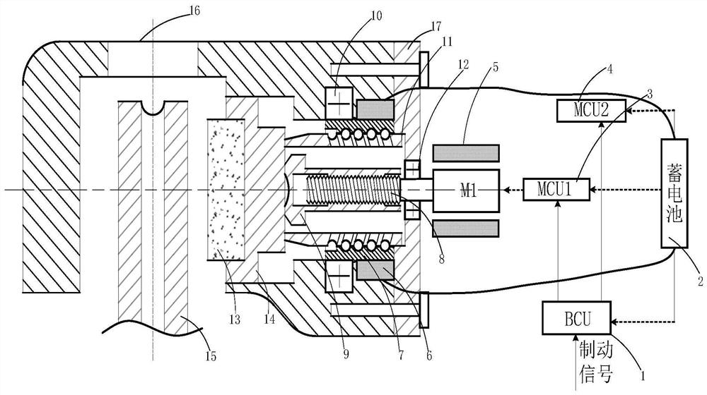
[0051] figure 1 The high stable EMB line control system suitable for ABS includes an electronic control unit and a brake unit.

[0052] The electronic control unit includes a BCU (brake control unit) 1, the first motor controller 3 (MCU 1), and the second motor controller 4 (MCU 2), and BCU1 are connected to the first motor controller 3 and the second motor controller 4 signal connection. The BCU1 receives the brake pedal signal (brake pedal opening degree λ), the vehicle speed signal V, the wheel speed sensor emits the wheel speed signal W and the motor feedback current signal and the motor operating status information, and the information collection before controlling, further By calculating the brake signal, the motor torque output signal and the slip rate, the BCU1 transmits the motor torque output signal to the fi...


PUM


Abstract

The invention provides a high-stability EMB brake-by-wire system suitable for an ABS and a control method of the high-stability EMB brake-by-wire system, and belongs to the technical field of automobile braking. The brake-by-wire system comprises an electronic control unit and a brake unit. The electronic control unit comprises a BCU, a first motor controller and a second motor controller. The brake unit comprises a first motor, a second motor, a threaded screw transmission part, a ball screw transmission part, a friction plate and a brake disc, the first motor is arranged on the outer side ofthe brake shell, and the second motor is arranged in the brake shell. A dual-motor structure is adopted, and dual-motor redundancy is achieved on the premise that brake-by-wire is achieved; during ABS anti-lock, the characteristics of self-locking of the threaded screw transmission part and non-self-locking of the ball screw transmission part are utilized, so that the first motor does not need locked-rotor braking torque, the second motor does not need to rotate reversely to release braking torque, the anti-lock purpose is achieved, the service life of the motor is prolonged, and braking is more stable.

Description

Technical field [0001] The present invention relates to the field of automotive braking technologies, and more particularly to high stable EMB (Electronic Brake System, Electronic Machinery Brake System, Electronic Mechanical Brake System) of ABS (Antilock Brakesystem, Brake Death System) and Its Control Method. . Background technique [0002] The brake system is one of the important components of the automobile, which directly affects the form of safety in the car. The line control system is divided into two categories of EHB (Electro Hydraulic Braking, Electronic Hydraulic Braking, EMB, the EHB system is the multi-purpose, multi-form brake system, and the electronic system for combining the electronic system and the hydraulic system. The hydraulic system provides power as a spare system; the EMB system can be considered as an improved product of the EHB system, mainly consisting of wheels brake modules, central electronic control unit, and electronic pedal module, compared to t...

Claims


Application Information

Patent Timeline
Patent Type & Authority Applications(China)
IPC IPC(8): B60T13/74
CPCB60T13/74B60T13/746
Inventor 王峰叶鹏徐兴倪少勇阙红波汪跃中
Owner JIANGSU UNIV
Why Eureka
Try Eureka