Integrated self-lubricating carrier roller structure for medium-thickness plate roller type cooling bed

A roller-type, self-lubricating technology, applied in the direction of the cooling bed, bearings, shafts, etc., can solve the problems of increased scrap rate, large gap between the shaft sleeve and the idler shaft, and insufficient lubrication, so as to prolong the service life and prevent dust from entering Effects within the structure

Pending Publication Date: 2021-03-26
辽宁德润新材科技有限公司
View PDF0 Cites 0 Cited by
  • Summary
  • Abstract
  • Description
  • Claims
  • Application Information

AI Technical Summary

Problems solved by technology

The traditional roller bushing is copper-based plus graphite molecules, and there is no adsorption capacity during the lubrication process. The release is too fast, and the lubrication effect is completely lost during the long-term sliding process, resulting in wear of the bushing, or even complete wear of the bushing. Direct friction between roller and shaft
The crux of the problem is that the bushing and the shaft are stuck due to insufficient lubrication between the bushing and the shaft, coupled with the thermal expansion of the slab, which eventually causes the jamming
In addition, due to the high-pressure, high-temperature and dusty working environment, dust can easily enter the device, which will also cause the shaft sleeve to be stuck and the gap between the shaft sleeve and the idler shaft to be too large
The jamming of idler rollers will cause problems such as strain and scratches on the finished slab, and increase the scrap rate

Method used


Image

  • Integrated self-lubricating carrier roller structure for medium-thickness plate roller type cooling bed
  • Integrated self-lubricating carrier roller structure for medium-thickness plate roller type cooling bed
  • Integrated self-lubricating carrier roller structure for medium-thickness plate roller type cooling bed

Examples


Embodiment Construction

[0018] The present invention will be further described below in conjunction with the accompanying drawings, but the scope of protection of the present invention is not limited to the accompanying drawings.

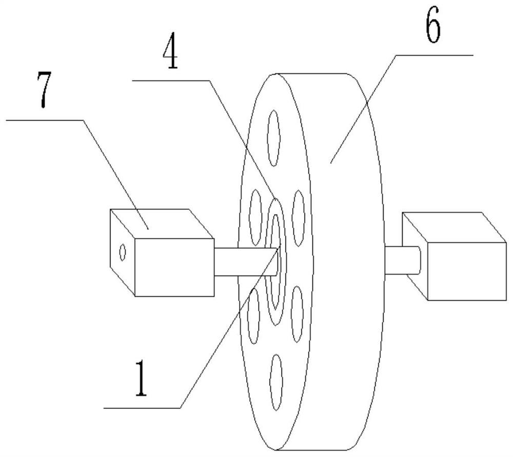
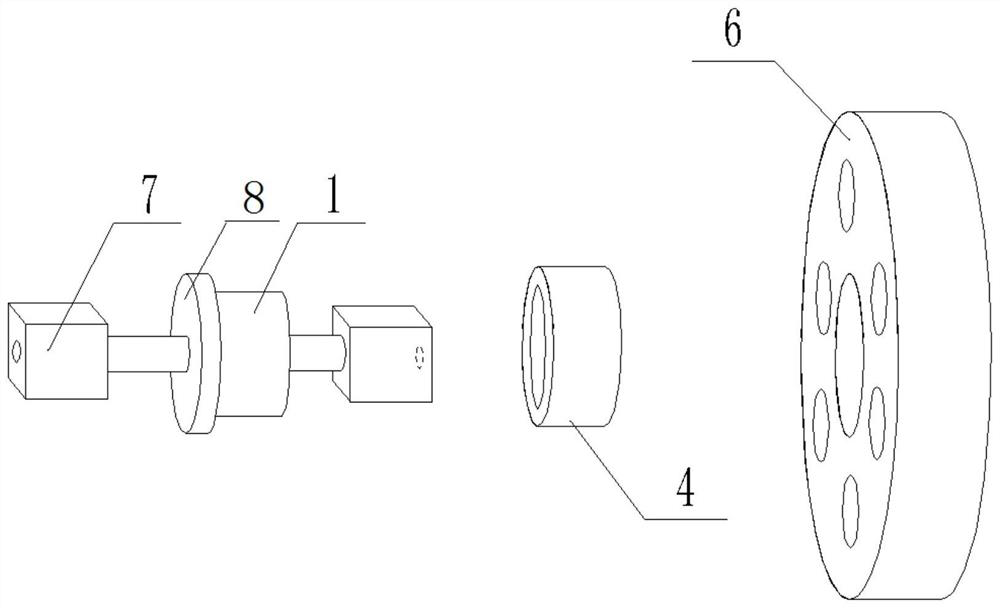
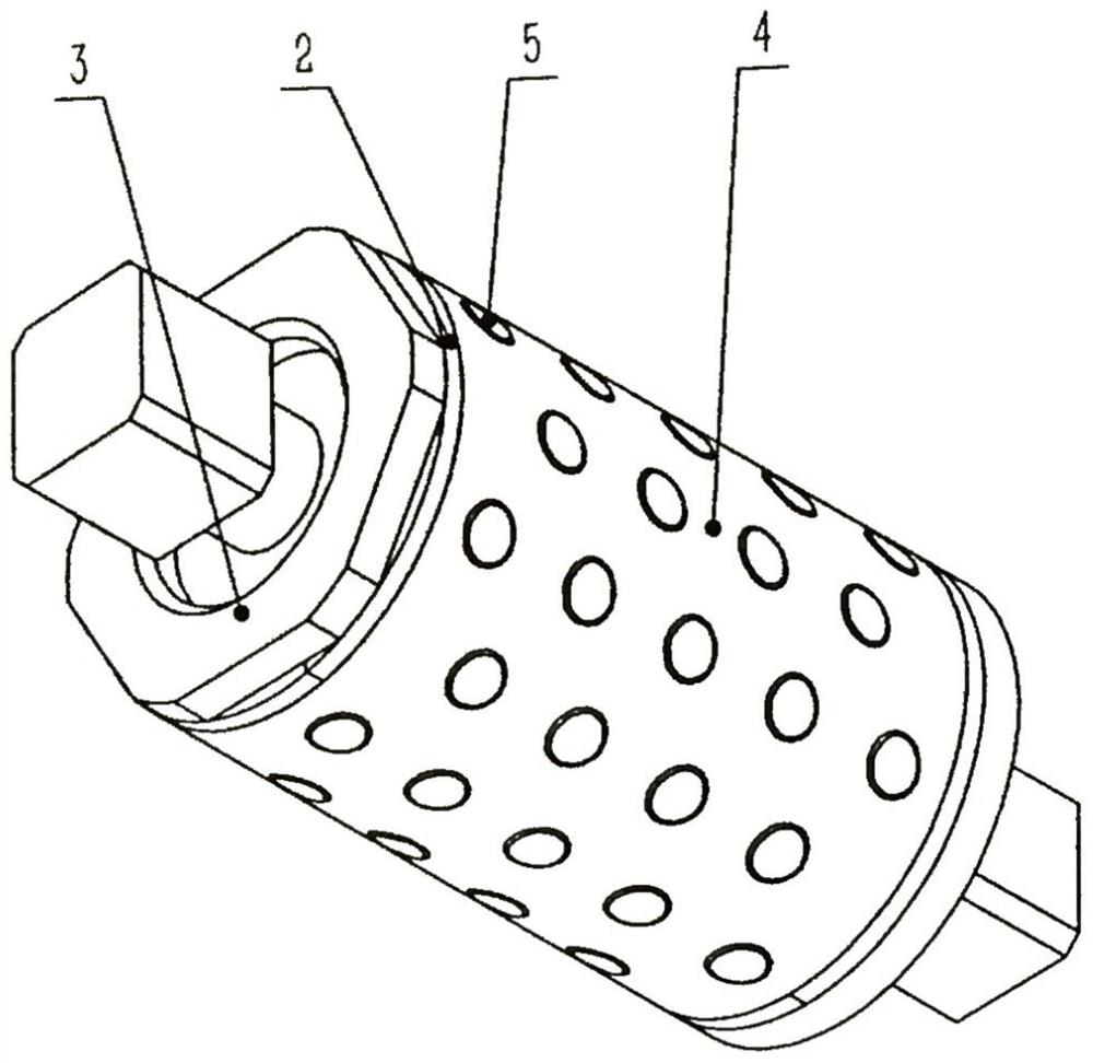
[0019] image 3 It is a structural schematic diagram of the integrated self-lubricating roller of the present invention, Figure 4 It is a schematic plan view of the integrated self-lubricating idler of the present invention. As shown in the figure, the integrated self-lubricating idler structure of the present invention for the roller type cooling bed of medium and thick plates includes a shaft 1 and a bushing 4. The shaft 1 Both ends are mounting heads 7, which are connected and installed on the cooling bed. The shaft 1 and the bushing 4 are integrally installed. One end of the shaft 1 is a protruding retaining ring 8, and the bushing 4 is set on the shaft 1 to be flush with the retaining ring 8. , the other end of the shaft 1 is machined with a section of external thre...


PUM


Abstract

The invention relates to the technical field of manufacturing of high-performance, high-reliability, long-service-life sealing, transmission, fastening, hydraulic and pneumatic products or elements, in particular to an integrated self-lubricating carrier roller structure for a medium-thickness plate roller type cooling bed. The integrated self-lubricating carrier roller structure comprises a shaftand a shaft bushing, installation heads are arranged at two ends of the shaft, the shaft is connected to and installed on a cooling bed, and the shaft and the shaft bushing are integrally installed.One end of the shaft is a protruding baffle ring, the shaft bushing is flush with the baffle ring on the shaft, a section of external thread is machined at the other end of the shaft, a sealing ring is additionally arranged on the end face, a fixing nut is just screwed into the external thread, and the end face is sealed through the sealing ring. Round holes are evenly formed in the side face of the shaft bushing, lubricating blocks are fixed in the round holes, and the shaft bushing with the lubricating blocks plays a self-lubricating role. The integrated self-lubricating structural design isadopted, a compact rolling friction mode is kept all the time, metal ceramic is cladded on an abrasion face through the metal surface engineering technology for strengthening treatment, multi-stage sealing is achieved, dust is prevented from entering the structure, and the service life of equipment is prolonged.

Description

technical field [0001] The invention relates to the technical fields of high performance, high reliability and long life sealing, transmission, fastening, hydraulic and pneumatic products or components manufacturing, and in particular to an integrated self-lubricating idler roller used for medium and thick plate roller cooling beds structure. Background technique [0002] The rolling plate cooling bed is a cooling bed composed of circular rolling plates with the same diameter. The circular rolling plate (roller) is fixed on the shaft concentrically or eccentrically with the transmission shaft. The total cooling table is arranged in rows and staggered. Thick plate cooling equipment that moves on a rotating circular roller and is cooled by flowing air. The rolling plate cooling bed has the advantages of small scratches on the lower surface of the steel plate, high cooling efficiency, less faults, easy operation and maintenance, and low equipment investment. [0003] In the t...

Claims


Application Information

Patent Timeline
Patent Type & Authority Applications(China)
IPC IPC(8): F16C13/02F16C33/04F16C33/74B21B43/04
CPCB21B43/04F16C13/02F16C33/043F16C33/74F16C2322/12
Inventor 孙开宇李睿魏世丞王玉江辛蔚
Owner 辽宁德润新材科技有限公司
Why Eureka
Try Eureka