
Antenna structure and electronic equipment

An antenna structure and antenna technology, applied in the connection of antenna grounding switch structures, antenna equipment with additional functions, antennas, etc., can solve the problems that the antenna structure cannot cover two same frequency bands at the same time, and the isolation of two-way signals cannot be guaranteed. , to achieve the effect of reducing occupied space and realizing space reuse

Active Publication Date: 2021-03-30
HUAWEI TECH CO LTD
View PDF10 Cites 3 Cited by
  • Summary
  • Abstract
  • Description
  • Claims
  • Application Information

AI Technical Summary

Problems solved by technology

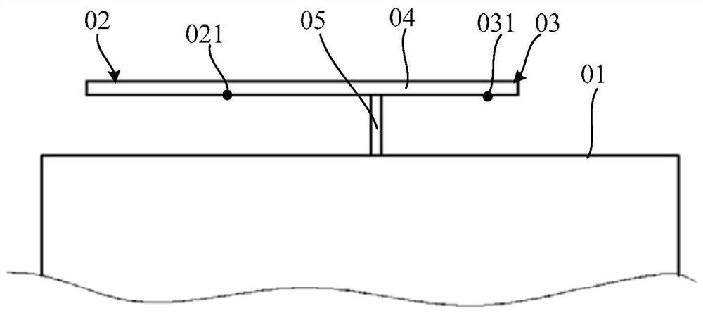
[0004] Since the first antenna 02 and the second antenna 03 share the same radiator 04, the signal frequency bands fed by the first feeding position 021 and the second feeding position 031 should be different, if the first feeding position 021 and the second feeding position 031 The signal of the same frequency band is fed into the second feed position 031, and the isolation of the two signals cannot be guaranteed, so that figure 1 Antenna structures of the type shown cannot cover two of the same frequency bands at the same time

Method used


Image

  • Antenna structure and electronic equipment
  • Antenna structure and electronic equipment
  • Antenna structure and electronic equipment

Examples


Embodiment Construction

[0045] In the embodiments of the present application, the terms "first" and "second" are used for description purposes only, and cannot be understood as indicating or implying relative importance or implicitly indicating the quantity of indicated technical features. Thus, a feature defined as "first" and "second" may explicitly or implicitly include one or more of these features.

[0046] In the embodiment of the present application, it should be noted that the term "electrical connection" should be understood in a broad sense, for example, it may be to realize current conduction through direct connection, or to realize electric energy conduction through capacitive coupling.

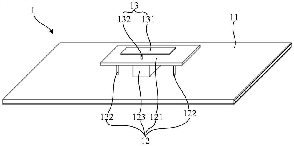
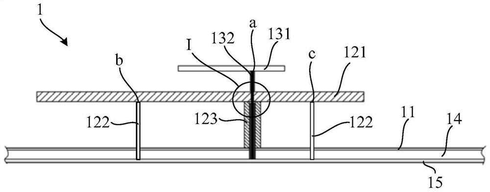
[0047] An embodiment of the present application provides an electronic device, the electronic device includes an antenna structure 1, such as figure 2 As shown, the antenna structure 1 includes: a signal reference ground 11, a first antenna 12, and a second antenna 13; wherein, the first antenna 12 incl...


PUM


Abstract

The embodiment of the invention provides an antenna structure and electronic equipment, relates to the technical field of electronic equipment, and can enable the antenna structure to cover the same frequency band while integrating two antennas to achieve spatial multiplexing. The antenna structure comprises a signal reference ground, a first antenna and a second antenna, wherein the first antennacomprises a first radiator and a first feeder line, the first radiator is provided with a first feeding position, the first radiator is fed from the first feeding position through the first feeder line, and the first radiator is electrically connected with the signal reference ground; the second antenna comprises a second radiator and a second feeder line, the second radiator is provided with a second feeding position, the second radiator is fed from the second feeding position through the second feeder line, the second feeder line comprises a signal transmission line and a signal reference ground line, and the signal reference ground line is electrically connected with the first radiator. The antenna structure provided by the embodiment of the invention is applied to the electronic equipment.

Description

technical field [0001] The present application relates to the technical field of electronic equipment, and in particular to an antenna structure and electronic equipment. Background technique [0002] In recent years, with the rapid development of wireless communication technology, there are more and more frequency band standards for antenna structures in electronic devices such as mobile phones, tablets, notebooks, and routers. In order to install these antenna structures in electronic devices with limited space, multiple antennas can be used Integrate into one for spatial multiplexing. [0003] example, figure 1 Shown is an antenna structure (also called a multi-feed point antenna) in the prior art. The antenna structure includes: a signal reference ground 01, a first antenna 02 and a second antenna 03; the first antenna 02 includes a first radiation The first radiator has a first feeding position 021, and the first radiator is fed with electricity by the first feeding p...

Claims


Application Information

Patent Timeline
Patent Type & Authority Applications(China)
IPC IPC(8): H01Q1/36H01Q1/48H01Q1/50H01Q1/52H01Q1/44H01Q1/24H01Q1/22
CPCH01Q1/36H01Q1/48H01Q1/50H01Q1/521H01Q1/44H01Q1/242H01Q1/2258H01Q1/22H01Q21/28H01Q9/0414H01Q9/0421H01Q1/243H01Q9/045
Inventor 马宁赖奔潘鑫
Owner HUAWEI TECH CO LTD
Learn More