Multi-column and multi-tool high-efficiency composite machining center

A compound machining center, high-efficiency technology, applied in the direction of manufacturing tools, other manufacturing equipment/tools, etc., can solve the problems of poor levelness and low cutting efficiency of ordinary double-column vertical lathe beams, and achieve wide processing range and low cutting efficiency , the effect of good rigidity

Active Publication Date: 2022-07-08
徐绍波
View PDF9 Cites 0 Cited by
  • Summary
  • Abstract
  • Description
  • Claims
  • Application Information

AI Technical Summary

Problems solved by technology

[0005] The purpose of the present invention is to provide a multi-column multi-knife high-efficiency composite machining center, which overcomes the deficiencies of the prior art, adopts a multi-column multi-knife structure, sets a center column and a reinforced bracket to improve the rigidity of the equipment beam, and the tool holder is extremely symmetrical One positive and one reverse are set in pairs to balance the rotating cutting force. It can combine five functions of gantry milling, gear milling machine, radial arm drill, vertical lathe and floor boring and milling in one, and solve the problem of working table with a diameter of more than 10 meters. The cutting efficiency of large or super large vertical lathes is low, and the problem of poor horizontality of the beam of ordinary double-column vertical lathes

Method used


Image

  • Multi-column and multi-tool high-efficiency composite machining center
  • Multi-column and multi-tool high-efficiency composite machining center
  • Multi-column and multi-tool high-efficiency composite machining center

Examples


Embodiment Construction

[0020] The technical solutions in the embodiments of the present invention will be clearly and completely described below with reference to the accompanying drawings in the embodiments of the present invention. Obviously, the described embodiments are only a part of the embodiments of the present invention, rather than all the embodiments. Based on the embodiments of the present invention, all other embodiments obtained by those of ordinary skill in the art without creative efforts shall fall within the protection scope of the present invention.

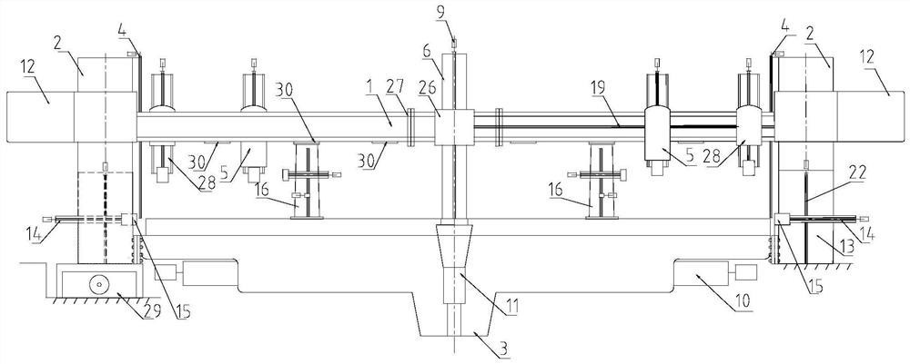
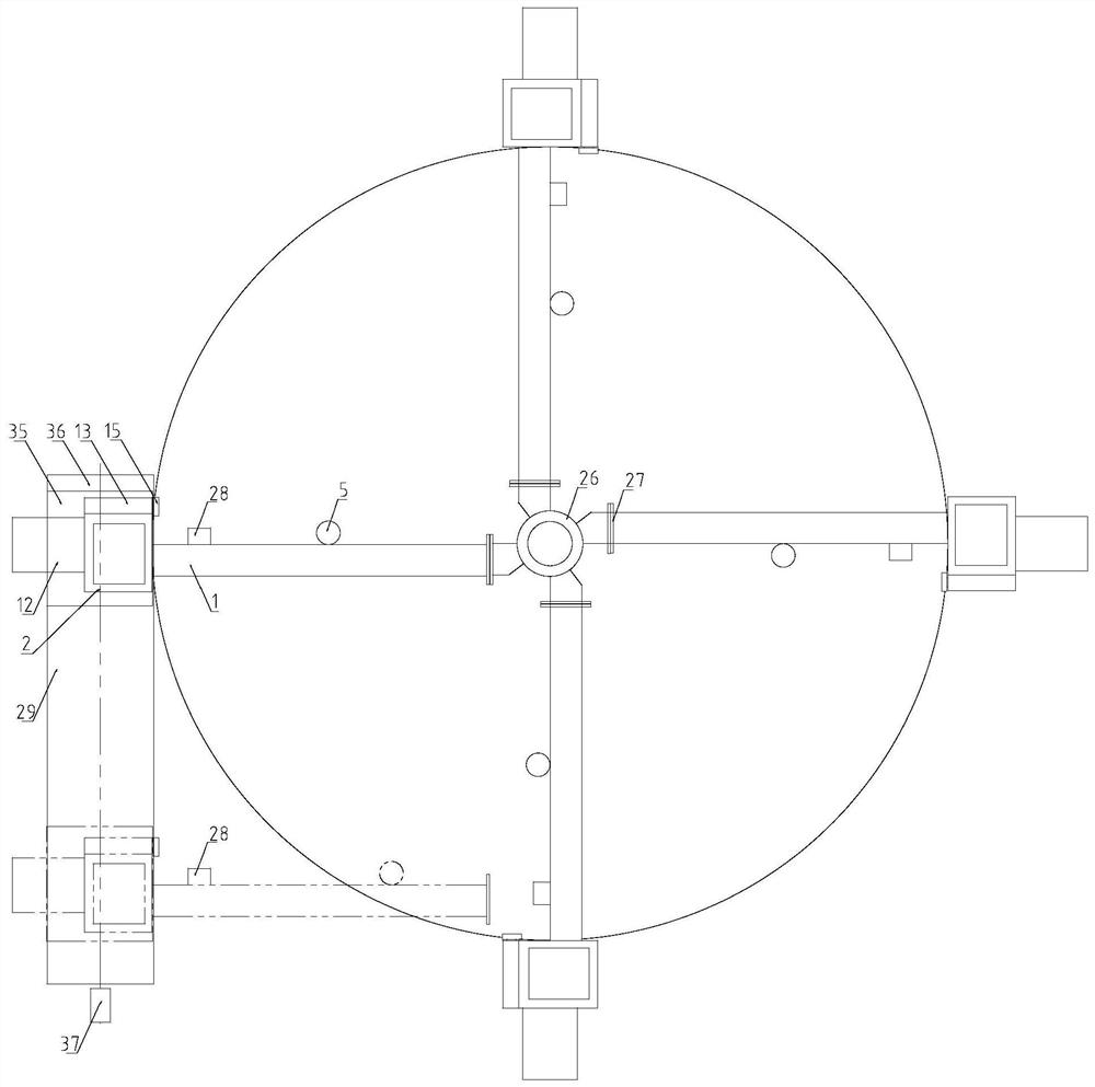
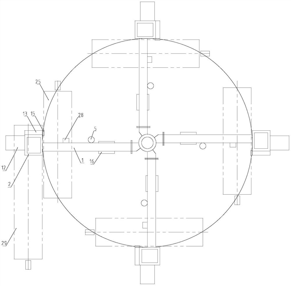
[0021] In the following embodiment, the vertical column lifting assembly 4, the boring and milling head 5, the main gearbox 10, the horizontal counterweight 12, the side tool rest 13, the side tool rest square ram 14, the auxiliary boring and milling head 15, the worm gear screw lift The mechanism 18 and the numerical control system are all existing commercial products. In the embodiment, the diameter of the workbench of this model i...


PUM


Abstract

The invention relates to the field of vertical lathes, in particular to a multi-column multi-tool high-efficiency composite machining center, comprising a beam, a column and a worktable, and a column lifting assembly is arranged between the beam and the column, and is characterized in that the column is 4-8 They are evenly arranged on the periphery of the worktable in the form of extremely symmetrical distribution; the worktable is provided with a central column in the center, and a central beam sleeve is arranged on the central column, and the central beam sleeve is connected with the lifting assembly of the central column. The flange is connected to the center beam sleeve, the lifting and lowering of the beam, the lifting and lowering of the boring and milling head on the beam, the horizontal movement of the boring and milling head and the turning tool holder, the column retraction operation of the column, and the rotation of the worktable are controlled by the numerical control system respectively. . Compared with the prior art, the beneficial effects of the present invention are as follows: equipped with different tools and accessories, it can realize five functions of gantry boring and milling, gear milling machine, radial drill, vertical turning and floor boring and milling, and becomes an efficient and multifunctional machine. The compound vertical lathe doubles the processing efficiency.

Description

technical field [0001] The invention relates to the field of vertical lathes, in particular to a large or super large multi-column multi-tool high-efficiency composite machining center. Background technique [0002] The vertical lathe is referred to as "vertical lathe". The vertical lathe is mainly used to process large and heavy workpieces with large diameter and short length. The single-arm mobile vertical lathe is an economical, light-duty and multi-functional lathe, which is developed into a large and heavy-duty lathe, but there are problems of uneven beam and resonance, which is a world problem. The beam of the extra-large double-column vertical lathe can remain horizontal when it is stationary, but it will show concave deformation to varying degrees during cutting work (especially during strong machining). It is an unsolved problem in the world. [0003] The Chinese utility model patent with the application number of 200720069104.3 discloses a single-column vertical ...

Claims


Application Information

Patent Timeline
Patent Type & Authority Patents(China)
IPC IPC(8): B23P23/02
CPCB23P23/02Y02P70/10
Inventor 徐绍波徐玉荣徐蓓蓓尚英奇刘禹含
Owner 徐绍波
Why Eureka
Try Eureka