Power battery rapid separation system and method

A technology of quick detachment and power battery, which is applied in the direction of power devices, electric power devices, electric vehicles, etc., can solve the problems of small battery box, large volume, and the inability to quickly detach the power battery from the car body, and achieve sliding synchronization and sliding No jamming, fast installation and disassembly

Pending Publication Date: 2021-04-02
ZHONGTONG BUS HLDG
View PDF0 Cites 0 Cited by
  • Summary
  • Abstract
  • Description
  • Claims
  • Application Information

AI Technical Summary

Problems solved by technology

[0005] The inventor found that in the existing method, most of the batteries are fixed in the car body by bolts, which cannot meet the requirement that the power battery can be quickly detached from the car body; This structure and arrangement is only suitable for large passenger cars with luggage compartments, and the battery box is small and arranged in multiple

Method used


Image

  • Power battery rapid separation system and method
  • Power battery rapid separation system and method
  • Power battery rapid separation system and method

Examples


Embodiment example

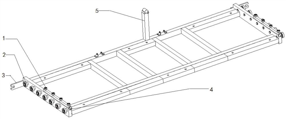
[0045] A preferred implementation case of the present disclosure is listed below, a power battery quick disengagement system, including a slidable bracket, a car body bracket fixed on the car body, and a quick locking device;

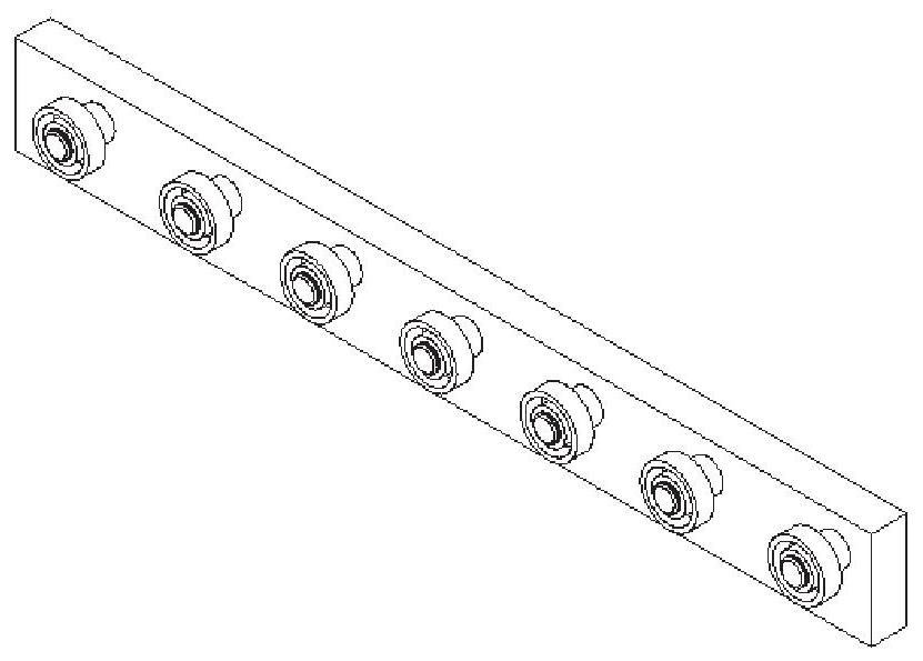
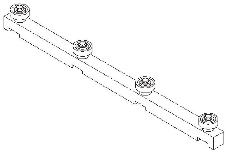
[0046] figure 1 The structure diagram of the slidable bracket described in this embodiment is shown in ; the slidable bracket includes a frame that uses bolts to fix the battery box. The internal components of the lower battery box meet its strength design requirements, and the sliding rollers and guide rollers installed on the frame, figure 2 The structural diagram of the sliding rollers in the slidable bracket described in this embodiment is shown in , image 3 The structural diagram of the guide rollers in the slidable bracket described in this embodiment is shown in ; the slidable rollers include two groups of several rollers, one set is arranged on the left and right side frames of the slidable cradle, and the rollers Arranged vertically on the ...

Embodiment 2

[0053] The purpose of this embodiment is to provide a method for quickly disconnecting a power battery.

[0054] A method for quickly disengaging a power battery, comprising:

[0055] The slidable bracket slides into the vehicle body bracket along the roller slideway, the taper pin fits seamlessly with the positioning sleeve, and the outermost frame of the slidable bracket and the vehicle body bracket are quickly locked The device is fixed and locked by a spring locking pin, and the slidable bracket is in a locked state;

[0056] When a crisis situation occurs, perform the step of quickly disengaging the battery, including pulling out the spring locking pin, loosening the fixing nut, and turning the bolt out of the positioning plate of the slidable bracket, and the slidable bracket is in a movable state;

[0057] The slidable bracket is pulled out of the vehicle body support through the traction rope, so as to realize the quick detachment of the battery.

[0058] Correspondi...

Embodiment 3

[0065] The purpose of this embodiment is to provide an electric vehicle.


PUM


Abstract

The invention provides a power battery rapid separation system and method. The system comprises a slidable bracket and a vehicle body support, a battery box is fixed to the slidable bracket, sliding rolling wheels and guide rolling wheels are arranged on frames at the two sides of the slidable bracket, the sliding rolling wheels are embedded in rolling wheel sliding ways in the vehicle body support, and the slidable bracket can horizontally move along the roller slideways; a taper pin is arranged in the innermost side frame, extending into the vehicle body bracket, of the slidable bracket, andis matched with a positioning sleeve fixed on the vehicle body bracket; and the frame in the outermost side of the slidable bracket and the vehicle body bracket are fixed through a quick locking device. According to the scheme, rapid installation of the battery can be guaranteed, the normal operation requirement can be met, the battery can be rapidly separated from a vehicle body when a dangeroussignal occurs in the battery, and injuries to passengers and the vehicle are avoided.

Description

technical field [0001] The present disclosure relates to the technical field of electric commercial buses, in particular to a system and method for quickly detaching a power battery. Background technique [0002] The statements in this section merely provide background information related to the present disclosure and do not necessarily constitute prior art. [0003] Power batteries are the core components of electric vehicles. Lithium batteries, which are widely used at present, form current through internal electrochemical reactions to supply drive motors; with the large-scale popularization of electric vehicles, the safety requirements for electric vehicles are getting higher and higher. When batteries In the case of internal short circuit or thermal runaway, if the battery can be separated from the vehicle body in time, it will avoid combustion and explosion of the vehicle, avoid major accidents and personal injury, so it is necessary to design a system that can quickly ...

Claims


Application Information

Patent Timeline
IPC IPC(8): B60K1/04B60L3/00
CPCB60K1/04B60L3/00
Inventor 房继刚张传谦梁浩天任冠欣张清南
Owner ZHONGTONG BUS HLDG
Why Eureka
Try Eureka