Supercharge Your Innovation With Domain-Expert AI Agents!

Graphite part structure for optical fiber drawing furnace

A technology of drawing furnace and graphite parts, applied in the field of optical fiber production, can solve the problems of reducing heating efficiency, graphite dust deposition, complex structure, etc., and achieve the effects of simplifying operation difficulty, reducing cost, and improving optical fiber quality

Active Publication Date: 2021-04-02
TONGDING INTERCONNECTION INFORMATION CO LTD
View PDF8 Cites 1 Cited by
  • Summary
  • Abstract
  • Description
  • Claims
  • Application Information

AI Technical Summary

Problems solved by technology

[0002] In the field of optical fiber production, optical fibers are obtained by melting optical fiber preforms. Optical fiber preforms are melted under certain high temperature conditions to form filaments, which are drawn and coated to form commercial optical fibers. Optical fiber drawing furnaces are preform heating machines. Most manufacturers will use intermediate frequency Induction furnace, the graphite parts in the drawing furnace are heated by the eddy current effect to form a high-temperature area, and the preform in the high-temperature area will gradually melt. Since graphite is easy to react with oxygen at high temperature, it will be injected into the graphite parts of the drawing furnace during production. A certain amount of protective gas is used to isolate the air. The structural design of graphite parts will change the temperature field in the drawing furnace. Different temperature field conditions have a great impact on the quality of optical fiber products. At the same time, if the design is unreasonable, the life of graphite parts will be reduced.
[0003] At present, the structure of graphite parts designed by most manufacturers in the industry consists of 6 parts, namely upper gas ring, lower gas ring, center tube, muffler tube, center tube insulation layer and muffler tube insulation layer. The structure is relatively complicated. Graphite dust is easy to deposit on the outer wall of the gas ring, and it is not easy to clean. It is necessary to regularly dismantle the drawing furnace and take out the graphite parts for cleaning. At the same time, due to structural reasons, the upper and lower gas rings need to cooperate to form a diversion effect, which often increases the inner diameter of the center. The inner space of the graphite part increases, which reduces the heating efficiency, and requires more shielding gas to maintain the temperature field. In addition, in order to reduce the inner diameter of the central tube, the wall thickness of the upper gas ring is often designed to be thinner, but in the production process , the upper gas ring is most likely to contact air and cause oxidation loss. Generally, the life of the upper gas ring will be much lower than other graphite parts

Method used


Image

  • Graphite part structure for optical fiber drawing furnace
  • Graphite part structure for optical fiber drawing furnace
  • Graphite part structure for optical fiber drawing furnace

Examples


Embodiment

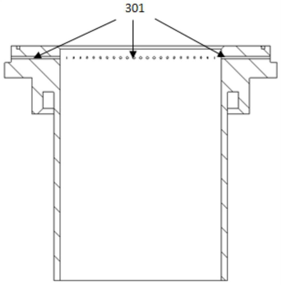
[0036] This embodiment provides a graphite piece structure for an optical fiber drawing furnace, such as figure 1 shown, including:

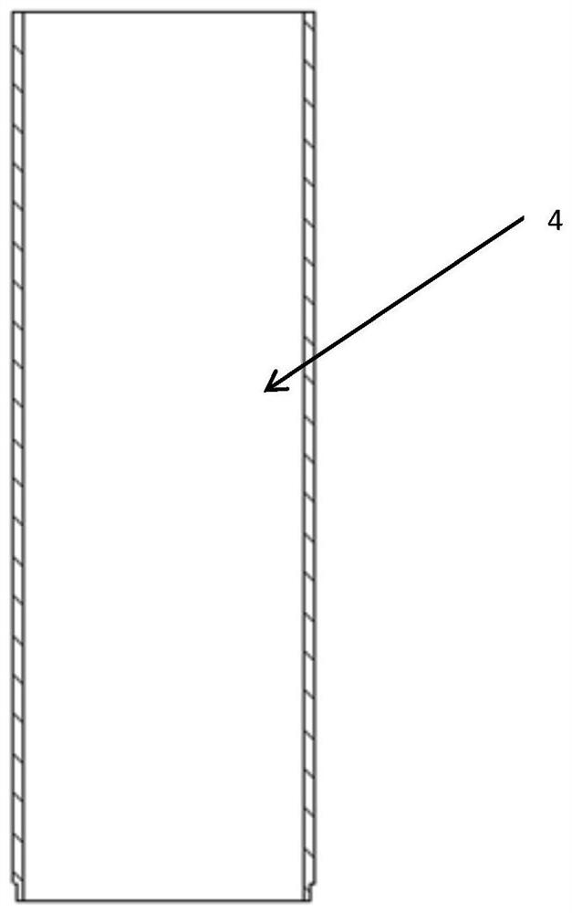
[0037] Gas ring 3, central tube 4, muffler tube 6, insulation layer 5, heat preservation bowl 7, the heat preservation bowl 7 is placed on the water plate at the bottom of the wire drawing furnace; the muffler tube 6 is inserted into the heat preservation bowl 7, and the edge is placed on The water plate at the bottom of the wire drawing furnace, the lower edge passes through the heat preservation bowl 7 and the water plate at the bottom of the wire drawing furnace; the central tube 4 is a straight cylindrical graphite piece, which falls on the muffler tube 6; the insulation layer 5 is cylindrical, and the On the outside of the central tube 4 and the muffler tube 6, it falls on the heat preservation bowl 7; the gas ring 3 is embedded in the central tube 4, and its upper edge falls on the water plate of the upper flange of the drawing furnace.

...


PUM


Abstract

The invention relates to a novel graphite part structure for an optical fiber drawing furnace. The structure comprises a gas ring, a central pipe, a muffle pipe, a heat-insulating layer and a heat-insulating bowl, the gas ring, the central pipe and the muffle pipe are all high-purity graphite products, the heat-insulating layer is graphite soft felt, and the heat-insulating bowl is graphite hard felt. The heat-insulating bowl, the muffle pipe, the central pipe, the heat-insulating layer and the gas ring are all designed to be cylindrical and are sequentially stacked, sleeved, assembled and placed on a water plate at the bottom of the fiber drawing furnace, the heat-insulating bowl and the heat-insulating layer are arranged on the outer side of the muffle pipe and the outer side of the central pipe in a sleeving mode to achieve heat insulation and heat preservation effects, the muffle pipe and the central pipe are stacked depends on the size and the step design, the outer diameter of the lower opening of the gas ring is slightly smaller than that of the central pipe, the gas ring is embed into the central pipe, equidistant through holes are formed around the upper opening of the gasring, and protective gas enters a drawing furnace graphite part through the through holes. The graphite part structure provided by the invention has the advantages that the cleaning operation difficulty is simplified, the service life of the graphite part is prolonged, and the shielding gas cost is reduced.

Description

technical field [0001] The invention relates to the technical field of optical fiber production, in particular to a graphite component structure for an optical fiber drawing furnace. Background technique [0002] In the field of optical fiber production, optical fibers are obtained by melting optical fiber preforms. Optical fiber preforms are melted under certain high temperature conditions to form filaments, which are drawn and coated to form commercial optical fibers. Optical fiber drawing furnaces are preform heating machines. Most manufacturers will use intermediate frequency Induction furnace, the graphite parts in the drawing furnace are heated by the eddy current effect to form a high-temperature area, and the preform in the high-temperature area will gradually melt. Since graphite is easy to react with oxygen at high temperature, it will be injected into the graphite parts of the drawing furnace during production. A certain amount of protective gas is used to isolate...

Claims


Application Information

Patent Timeline
IPC IPC(8): C03B37/029
CPCC03B37/029Y02P40/57
Inventor 沈小平祝君魏文涛白晓明
Owner TONGDING INTERCONNECTION INFORMATION CO LTD
Features
  • R&D
  • Intellectual Property
  • Life Sciences
  • Materials
  • Tech Scout
  • Unparalleled Data Quality
  • Higher Quality Content
  • 60% Fewer Hallucinations
Learn More