Air control cooling equipment for cooling cable material
A technology for cooling equipment and wind control, applied in heat exchange equipment, household refrigeration equipment, lighting and heating equipment, etc., can solve the problem of easy agglomeration of particles, and achieve the effect of preventing clogging and agglomeration
- Summary
- Abstract
- Description
- Claims
- Application Information
AI Technical Summary
Problems solved by technology
Method used
Image

Examples
Embodiment 1
[0028] A kind of air control cooling equipment for cable material cooling, such as Figure 1-Figure 3 As shown, it includes a base 1, a mounting frame 2, a cooling cylinder 3, a refrigeration mechanism 4, and a rotating mechanism 5. The mounting frame 2 is provided on the left side of the top of the base 1, and the cooling cylinder 3 is provided in the middle of the mounting frame 2. The upper part of the mounting frame 2 is left The side is provided with a refrigeration mechanism 4, and the top right side of the refrigeration mechanism 4 is provided with a rotating mechanism 5.
[0029] First of all, people pour the particles to be frozen into the cooling cylinder 3, start the refrigeration mechanism 4 to start freezing the particles, and then rotate the rotating mechanism 5 to make the particles cool evenly, so as to achieve the effect of uniform cooling of the frozen particles.
[0030] The refrigeration mechanism 4 includes a refrigeration device 40, an inlet valve 41, an ...
Embodiment 2
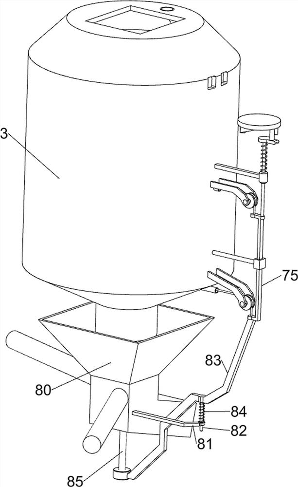
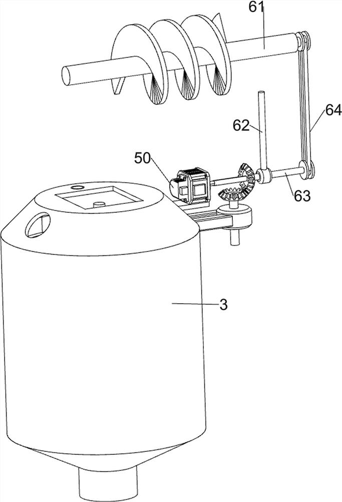
[0034] On the basis of Example 1, such as Figure 4-Figure 10 As shown, the uniform blanking assembly 6 is also included, and the uniform blanking assembly 6 includes a material transfer frame 60, a screw rod 61, a mounting rod 62, a rotating rod 63, a second transmission assembly 64 and a hopper 65, and the top of the cooling cylinder 3 A material transfer frame 60 is provided, and the internal rotation of the material transfer frame 60 is provided with a screw rod 61. The right side of the bottom of the material transfer frame 60 is connected with a mounting rod 62, and the mounting rod 62 is rotatably provided with a rotating rod 63. The rotating rod 63 is connected to the servo motor. The right end of the output shaft of the motor 50 is connected, the second transmission assembly 64 is connected between the screw rod 61 and the rotating rod 63 , and a lower hopper 65 is arranged on the upper right part of the material transfer frame 60 .
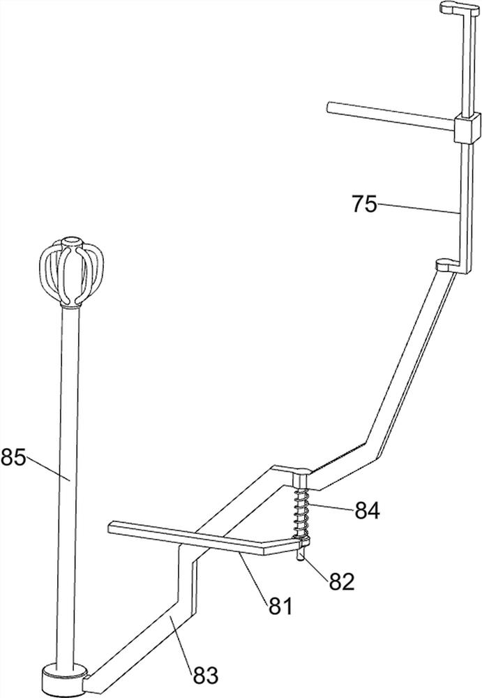
[0035]Also include shaking assemb...
PUM
 Abstract
Description
Claims
Application Information